2.12 Outdoor sensor
The outdoor sensor is required for the heat pump to
operate correctly.
Consult the tting instructions on the packaging.
Place the sensor on the coldest part, generally the
northern or north-eastern side.
In any case, it must not be exposed to the morning sun.
It must be installed so as to be easily accessible but at
least 2,5 m from the oor.
It is essential that it avoid any sources of heat such as
ues, the upper parts of doors and windows, proximity
to extraction vents, the underneath of balconies and
under-eave areas, which would isolate the sensor from
variations in the outdoor air temperature.
- Connect the outdoor sensor to the connector X84
(terminals M and B9) on the heat pump control board.
2.13 Room thermostat
and/or room control unit
The room thermostat (room control unit) is optional.
Consult the tting instructions on the packaging.
The sensor must be installed in the living room area on
a very uncluttered wall. It must be installed so as to be
easily accessible.
Avoid direct sources of heat (chimney/ue, television,
cooking hobs), draughty areas (ventilation, door, etc.).
Air leaks in the seals in the constructions are often
translated into cold air blowing through the electrical
conduits. Lag the electrical conduits if there is a cold
draught on the back of the IR sensor.
2.13.1 Installing a room sensor
• Room thermostat T37
- Connect the sensor to the X86 connector of the heat
pump’s regulator board using the connector provided
(terminals B2, M and B1).
" In the case of 2 heating circuits, The sensor is
connected to the card which corresponds to the
regulated heating circuit.
• Room thermostat T55
- Connect the sensor to the X86 connector of the heat
pump’s regulator board using the connector provided
(terminals 1, 2).
• Room thermostat radio T58
- Connect the wireless room thermostat radio to the
connector X60.
2.13.2 Installing a room control unit
• Room control unit T75
- Connect the sensor to the X86 connector of the heat
pump’s regulator board using the connector provided
(terminals 1, 2 and 3).
• Room control unit radio T78
- Connect the wireless room control unit radio to the
connector X60.
2.13.3 Fan convectors or dynamic radiators area
If the installation is equipped with fan convector or
dynamic radiators, Do not use a room sensor in the
area.
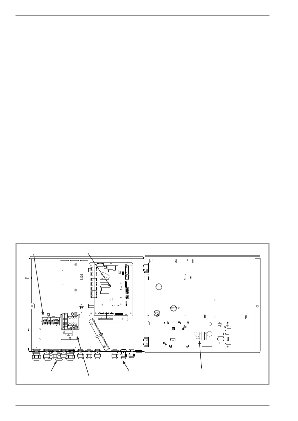
gure 34 - Access to hydraulic model electric box and description
230 V
L
N
L N
2
4
HP regulator
Cable grommet
(Power)
Interface card
Cable grommet
(sensors)
Relay
+ DHW Terminal blocks
Terminal blocks
Installation and operating manual "1578 - EN"
Heat Pump alféa extensa duo +
- 32 -
 Loading...