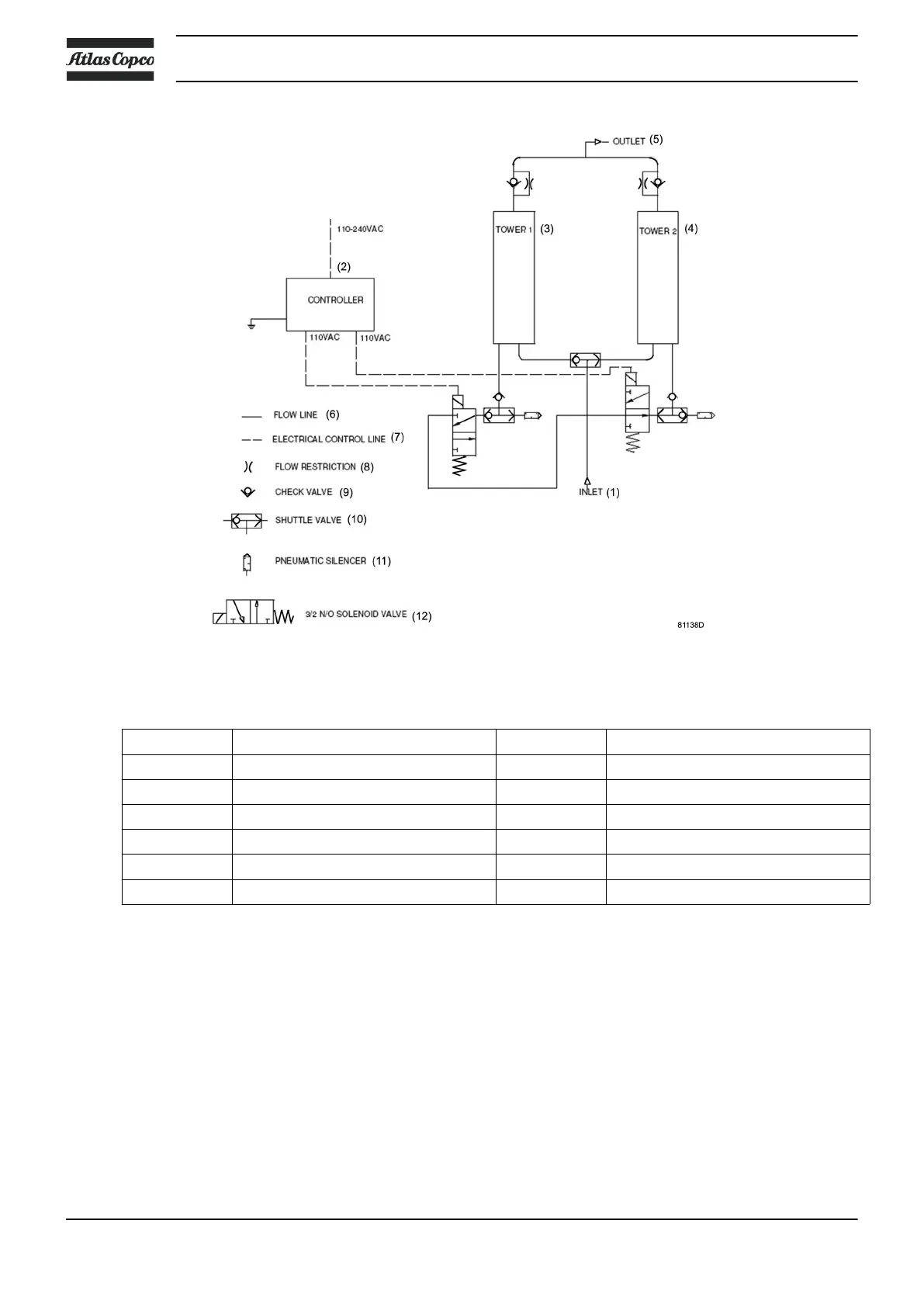
Flow diagram
Reference Designation Reference Designation
1 Air inlet 7 Electrical control line
2 Controller 8 Flow restriction
3 Left desiccant tower 9 Check valve
4 Right desiccant tower 10 Selector valve
5 Air outlet 11 Pneumatic silencer
6 Flow line 12 Solenoid valve
Operation principle
The operation cycle of the dryer is repetitive and is controlled by a factory-set timer. While the desiccant in
one tower dries the compressed air, the desiccant in the second tower is being regenerated. Regeneration of
the desiccant is achieved by means of purge air from the drying tower.
The compressed air entering the dryer is led to one of the towers by means of the bottom selector valve.
The position of the selector valve depends on the condition (activated or not) of the solenoid valves. As the
air flows upwards through the tower, the desiccant adsorbs the water vapour and the compressed air is
dried.
Once the top of the tower is reached, the air leaves the dryer via the check valve.
Instruction book
12 2920 7083 21