A small portion of the dried air passes a nozzle, expands to atmospheric pressure and flows downwards
through the other tower, regenerating (drying) the desiccant. A nozzle for operation of the dryer at 7 bar is
installed as standard. Alternative nozzles for use at other operating pressures are available as sales kit.
Please consult the spare parts list for specific information. The regeneration air is released via the
corresponding solenoid valve and the silencer. The solenoid valves are controlled by the timer.
After a pre-set period, the function of the towers is reversed. The fully regenerated tower will now dry the
air, while the desiccant in the other tower will be regenerated.
By default, the regeneration timer will restart from the beginning of the cycle in case of a power failure
during operation.
However, in case the input of remote control connector X3 (see section Electric diagram) is opened (by the
freeze contact), the dryer will "freeze" the drying cycle: purge air flow stops, both solenoid valves are
closed. When the contact, connected to connector X3 closes, the dryer will continue normal operation. This
feature can prevent loss of compressed air (purge air) when the compressor is not continuously running
loaded. On compressors with load/unload regulation, X3 can be connected to a voltage free contact of the
compressor (contact open when the compressor runs unloaded). If no free contact is available, an additional
voltage free contact should be installed on the load/unload contactor of the compressor to use this feature.
See section Electrical connections for more details.
Do not connect X3 when an air receiver is installed before the dryer.
X3 should only be connected when the air receiver is installed downstream of the dryer.
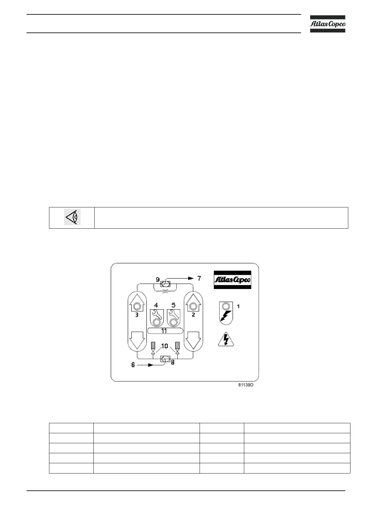
Control panel
Control panel with flow diagram
Reference Designation Reference Designation
1 LED <Power On> 7 Air outlet
2 LED <Right tower drying> 8 Inlet selector valve
3 LED <Left tower drying> 9 Outlet selector valve
4 LED <Service warning> 10 Solenoid valves
Instruction book
2920 7083 21 13