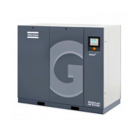
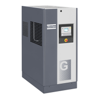
Electric cabinet of GA 75 VSD and GA 90 VSD, typical example
- Consult the sections Electric cable size,Installation proposals and Dimension drawings
- The following transport fixtures, painted red, must be removed:
•
Bolts (1)
•
Bushes (2)
•
Supports (3)
- Check that the electrical connections correspond to the local codes and that all wires are clamped tight
to their terminals.
The installation must be earthed and protected against short circuits by fuses of the inert type in all
phases. An isolating switch must be installed near the compressor.
- Check the voltage selecting wires at the primary side of transformer T1.
- Check the setting of circuit breaker (Q15). Also check that the switch on the circuit breaker is in position
I.
- Fit air outlet valve (AV); see section Introduction for the position of the valve.
Close the valve.
Connect the air net to the valve.
On compressors equipped with a dryer by-pass, fit the air outlet valve to the dryer by-pass pipe.
- Connect the condensate drain outlet(s) to a drain collector. See section Condensate system and in
case of an OSD see section Installation.
For Full-Feature units: also connect the condensate drain outlet of the dryer to a drain collector.
The drain pipes to the drain collector must not dip into the water. For draining of pure condensate water,
install an oil/water separator which is available from Atlas Copco as an option; see section OSD unit.
If the pipes have been fitted outside the room where freezing is possible, they must be insulated.
- For compressors with a DD or a DD and PD filter connect the automatic drain of the filters to a suitable
drain collector.
Instruction book
80 2920 1634 04
 Loading...
