2920 1449 00
28
Instruction book
Footnotes chapter 3
1) GR W are equipped with a ventilation fan in the roof. Check that
it withdraws heat from the bodywork.
2) GR Full-feature (provided with an integrated dryer) have two
condensate traps and two drain valves. Compressors without dryer
have one trap and one valve.
3) Customer’s installation.
4) If the compressor has only just stopped, wait one minute before
checking the level.
5) If the <<Load>> or <<Unload>> function is not indicated on the
bottom line of display (4-Fig. 3.5), press key <<Menu>> (5) until
function <<Main Screen>> appears above key (F1), then press
key <<Main Screen>>.
6) On compressors with optional OSD separator, a valve is fitted
underneath the condensate trap. Close the valve after repairing.
7) If function <<Show More>> is not indicated on the bottom line
of display (4-Fig. 3.5), press key <<Menu>> (5) until function
<<Main Screen>> appears above key (F1), then press key <<Main
Screen>>.
8) The compressor is automatically started and stopped if these start/
stop commands are programmed and activated; consult section
1.3.
9) Depending on the type of button.
1 Water inlet
2 Water outlet
3 Combined oil and air coolers
4 Regulating valve, water flow
Fig. 3.7 Water system of GR W (typical example)
3.8 Taking out of operation
At the end of the service life of the compressor, proceed as
follows:
1. Stop the compressor and close the air outlet valve.
2. Switch off the voltage and disconnect the compressor from
the mains.
3. Depressurize the compressor by opening valves (1 and 2-
Fig. 3.4) 2) 6) and loosening plug (3-Fig. 3.8) one turn.
4. Shut off and depressurize the part of the air net which is
connected to the outlet valve. Disconnect the compressor
air outlet pipe from the air net.
5. Drain the water, oil and condensate circuits.
6. Disconnect the compressor condensate piping from the
condensate drain net.
7. Disconnect the cooling water pipes from the compressor.
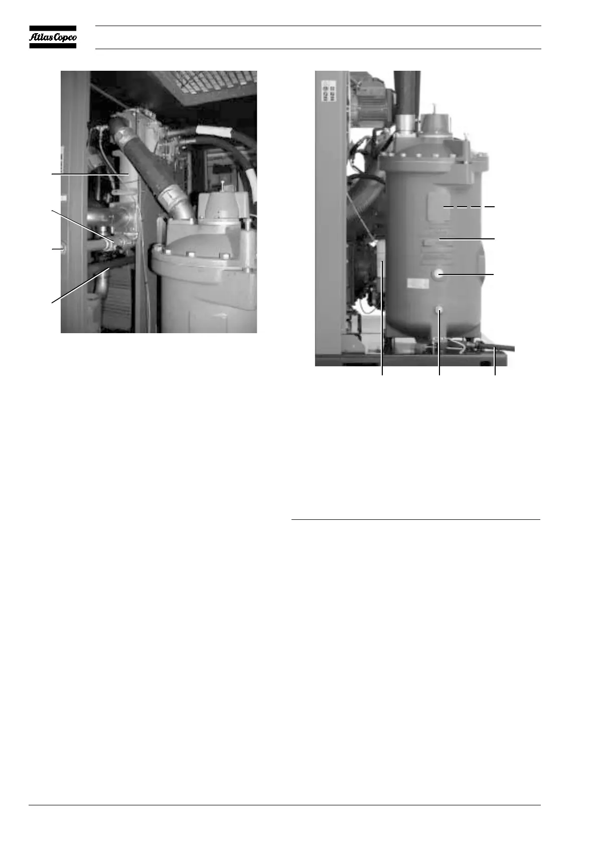
1 Oil separator element
2 Air receiver
3 Oil filler plug
4 Oil drain plug
5 Oil level sight-glass
6 Oil filters
Fig. 3.8 Air receiver
1
2
3
4
5
6
51444F
1
2
3
4
51477F
 Loading...


