Machine Composition 14
Atlas Cyclops
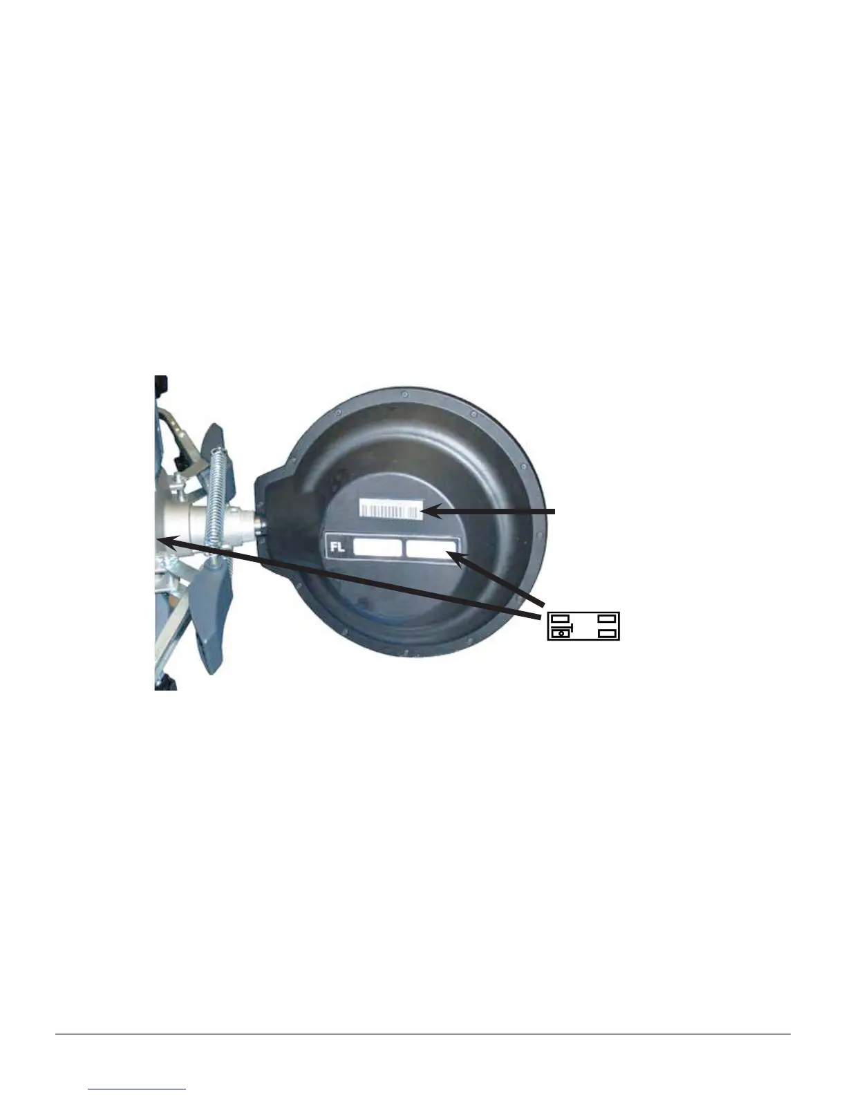
They are marked as Front Left and Right and Rear Left and Right, according to
the following table (see Figure 4):
FL = FRONT LEFT FR = FRONT RIGHT
RL = REAR LEFT RR = REAR RIGHT
Warning: the inclination of the target is determined at installation time, as
described in the part 5.2.3. Once the target is fi xed, fasten the clamps to the
wheel, making sure to position them vertically (see fi gure above).
Each target features a barcode as well, describing the characteristics of the 3D
object.
Clamp + target calibration and progressive production number for traceability,
are included also in the above code.
Figure 4
3D object
characterization
in space
Graphic symbol sticker
that shows the position
(see part 5.2.2), applied
both on target on clamp