Machine Composition 13
Atlas Cyclops
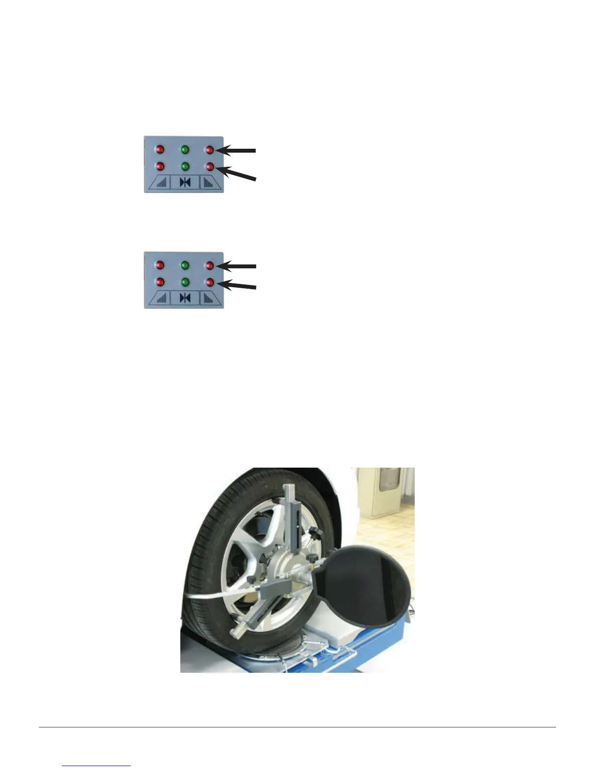
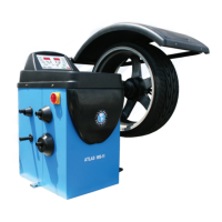
NOTE: Toe-in tolerance is always indicated by the lower LED row.
During rear adjustment, camber is always indicated by the upper LED row
During front adjustment, both camber and caster can be indicated by the upper
LED row. The “R” selection symbol should be set on the desired value (see 9.12).
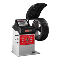
3.4 Clamps with target
The self-centering clamps with removable tabs will be fi tted with a target (see
Figure 3).
3-point self-centering
resting
clamps, fi tted with targets
(for
rims from 8’’ to
24’’)
Figure 3
LED’s on
FRONT SIDE
CAMBER/CASTER tolerance
(bring “R” selection symbol to the desired angle)
TOE tolerance
LED’s on
REAR SIDE
CAMBER tolerance
TOE tolerance