Transport And Installation 20
Atlas Cyclops
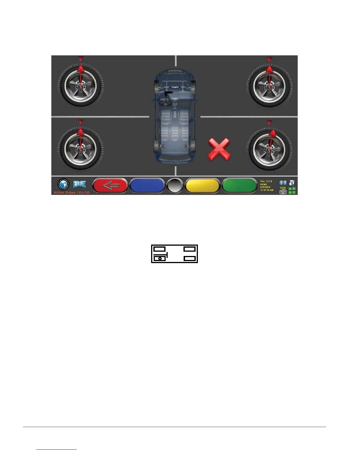
one or more targets are not properly orientated, an “X” symbol will appear (see
the rear-left wheel clamp in the example below). At the end of the alignment
procedure block the grub screw with the lock nut.
Figure 8
Apply the two stickers provided for each wheel clamp/target combination which
identify the front left (FL), front right (FR), rear left (RL) and right rear (RR)
positions. (See Figure 4)
5.2.3 Mounting the 3D camera unit supports
In order to be able to fi t the 3D camera unit supports, it is necessary to drill two
M8 holes on each side of the vehicle lift. This should be done in such a way that
the distance from the center of the 3D camera units to the center of the turn
plates is 3’ 11”.
If you need to work on vehicles with long wheelbases, turn plates can be moved
forward up to another 1’ 3”. The maximum distance from the rear wheels to the
center of the 3D camera units is 10’ 2”.