348
7679H–CAN–08/08
AT90CAN32/64/128
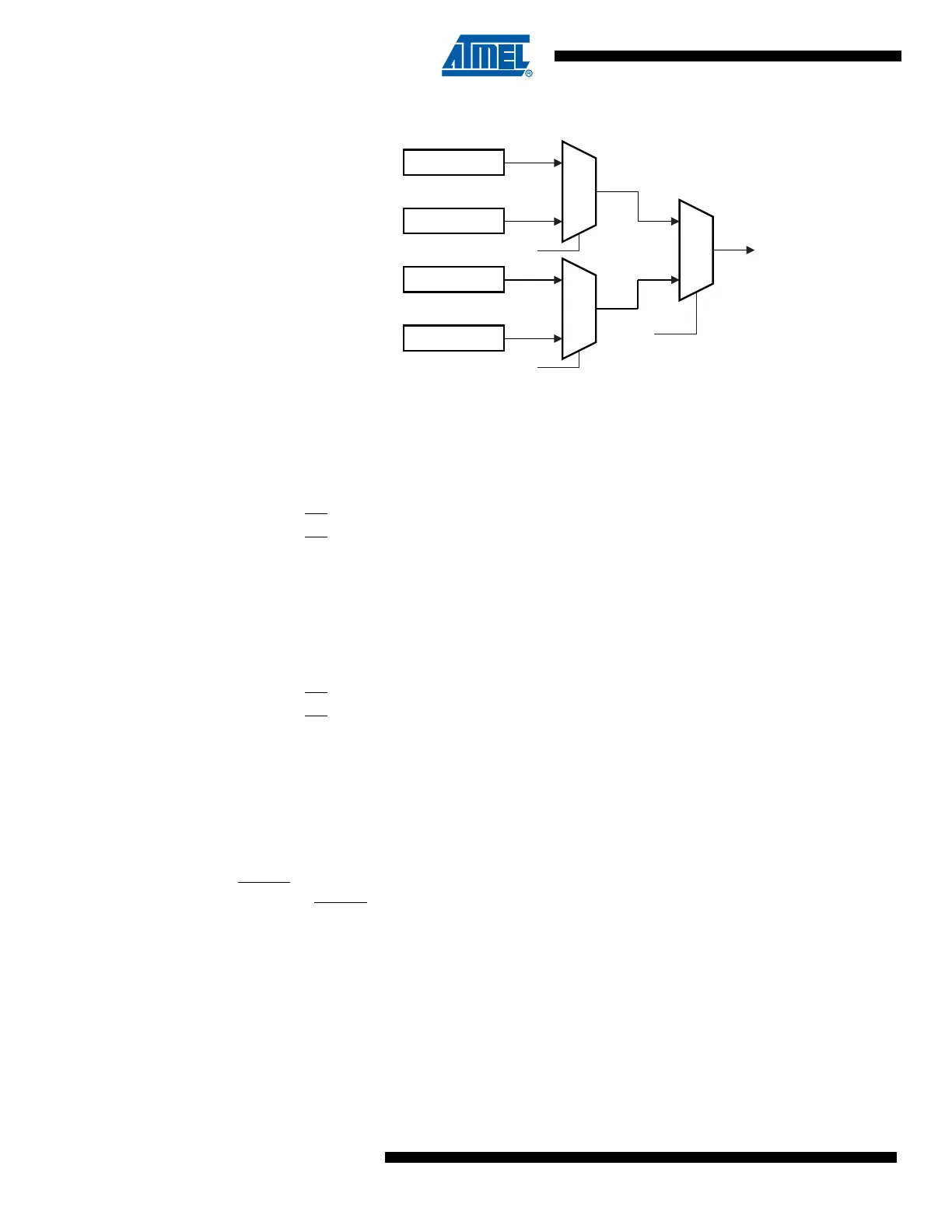
Figure 25-6. Mapping Between BS1, BS2 and the Fuse and Lock Bits During Read
25.6.13 Reading the Signature Bytes
The algorithm for reading the Signature bytes is as follows (refer to “Programming the Flash” on
page 342 for details on Command and Address loading):
1. A: Load Command “0000 1000”.
2. B: Load Address Low Byte (0x00 - 0x02).
3. Set OE
to “0”, and BS1 to “0”.
The selected Signature byte can now be read at DATA
.
4. Set OE
to “1”.
25.6.14 Reading the Calibration Byte
The algorithm for reading the Calibration byte is as follows (refer to “Programming the Flash” on
page 342 for details on Command and Address loading):
1. A: Load Command “0000 1000”.
2. B: Load Address Low Byte, 0x00.
3. Set OE
to “0”, and BS1 to “1”. The Calibration byte can now be read at DATA.
4. Set OE
to “1”.
25.7 SPI Serial Programming Overview
This section describes how to serial program and verify Flash Program memory, EEPROM Data
memory, Memory Lock bits, and Fuse bits in the AT90CAN32/64/128.
25.7.1 Signal Names
Both the Flash and EEPROM memory arrays can be programmed using the serial SPI bus while
RESET
is pulled to GND. The serial interface consists of pins SCK, MOSI (input) and MISO (out-
put). After RESET
is set low, the Programming Enable instruction needs to be executed first
before program/erase operations can be executed. NOTE, in Table 25-13 on page 349, the pin
mapping for SPI programming is listed. Not all parts use the SPI pins dedicated for the internal
SPI interface. Note that throughout the description about Serial downloading, MOSI and MISO
are used to describe the serial data in and serial data out respectively. For AT90CAN32/64/128
these pins are mapped to PDI (PE0) and PDO (PE1).
BS2
DATA
0
1
BS2
Extended Fuse Byte
Fuse Low Byte
0
1
Fuse High Byte
Lock Bits
BS1
0
1

 Loading...


