310
7679H–CAN–08/08
AT90CAN32/64/128
23.6.6 Scanning the ADC
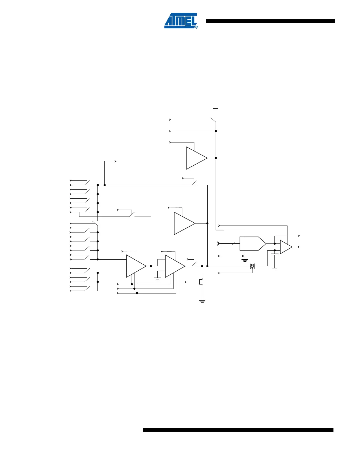
Figure 23-10 shows a block diagram of the ADC with all relevant control and observe signals.
The Boundary-scan cell from Figure 23-9 is attached to each of these signals. The ADC need
not be used for pure connectivity testing, since all analog inputs are shared with a digital port pin
as well.
Figure 23-10. Analog to Digital Converter
The signals are described briefly in Table 23-7.
+
-
AREF
PRECH
DACOUT
COMP
MUXEN_7
ADC_7
MUXEN_6
ADC_6
MUXEN_5
ADC_5
MUXEN_4
ADC_4
MUXEN_3
ADC_3
MUXEN_2
ADC_2
MUXEN_1
ADC_1
MUXEN_0
ADC_0
NEGSEL_2
ADC_2
NEGSEL_1
ADC_1
NEGSEL_0
ADC_0
EXTCH
+
-
+
-
10x 20x
10-bit DAC
ST
ACLK
AMPEN
2.56V
ref
IREFEN
AREF
VCCREN
DAC_9..0
ADCEN
HOLD
PRECH
GNDEN
PASSEN
ACTEN
COMP
SCTEST
ADCBGEN
To Comparator
G20
G10
1.22V
ref

 Loading...


