368
7679H–CAN–08/08
AT90CAN32/64/128
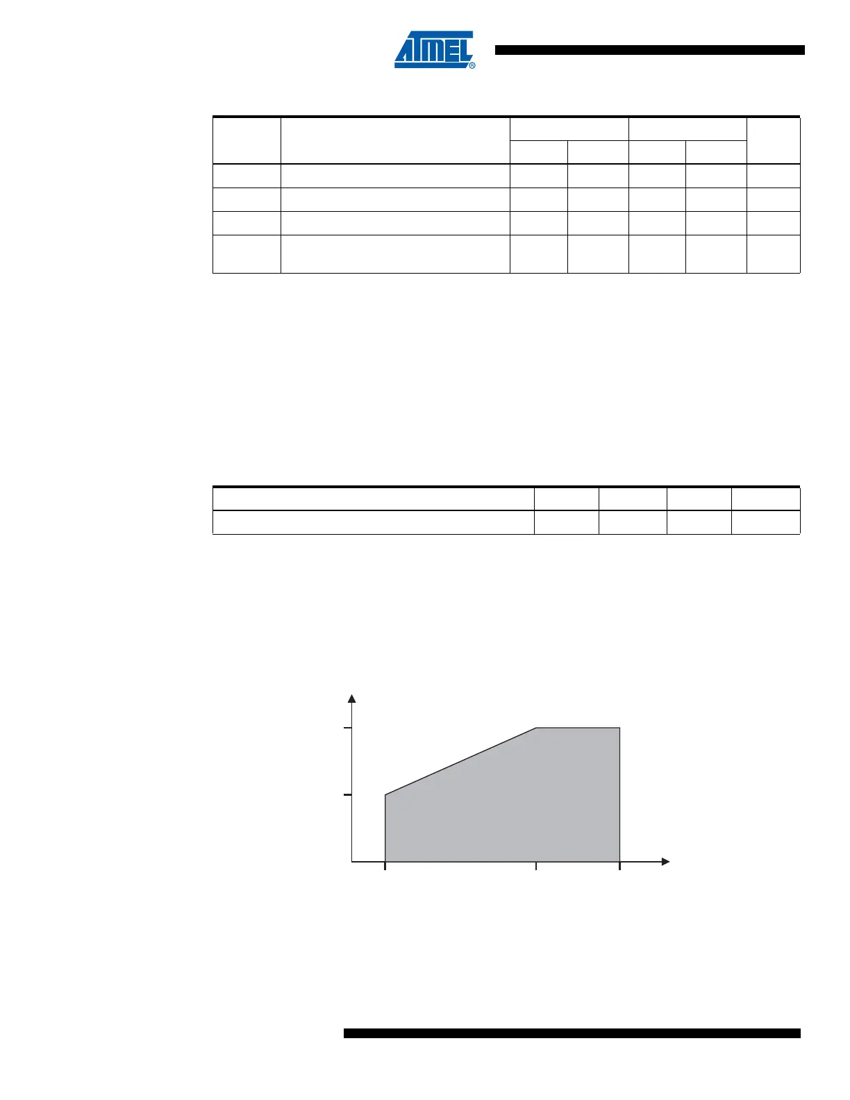
26.4 Maximum Speed vs. V
CC
Maximum frequency is depending on V
CC
. As shown in Figure 26-2., the Maximum Frequency
vs. V
CC
curve is linear between 1.8V < V
CC
< 4.5V. To calculate the maximum frequency at a
given voltage in this interval, use this equation:
To calculate required voltage for a given frequency, use this equation:
At 3 Volt, this gives:
Thus, when V
CC
= 3V, maximum frequency will be 9.33 MHz.
At 8 MHz this gives:
Thus, a maximum frequency of 8 MHz requires V
CC
= 2.7V.
Figure 26-2. Maximum Frequency vs. V
CC
, AT90CAN32/64/128
t
CLCX
Low Time 50 25 ns
t
CLCH
Rise Time 1.6 0.5 μs
t
CHCL
Fall Time 1.6 0.5 μs
Δt
CLCL
Change in period from one clock cycle
to the next
22%
Table 26-1. External Clock Drive (Continued)
Symbol Parameter
V
CC
= 2.7 - 5.5V V
CC
= 4.5 - 5.5V
Units
Min. Max. Min. Max.
Table 26-2. Constants used to calculate maximum speed vs. V
CC
Voltage and Frequency range a b Vx Fy
2.7 < VCC < 4.5 or 8 < Frequency < 16 8/1.8 1.8/8 2.7 8
Frequency
8
1.8
-------- 32.7–()8+• 9.33==
Voltage
1.8
8
-------- 88–()2.7+• 2.7==
Safe Operating Area
4.5V2.7V 5.5V
8 MHz
16 MHz
Frequency
Voltage

 Loading...


