417
7679H–CAN–08/08
AT90CAN32/64/128
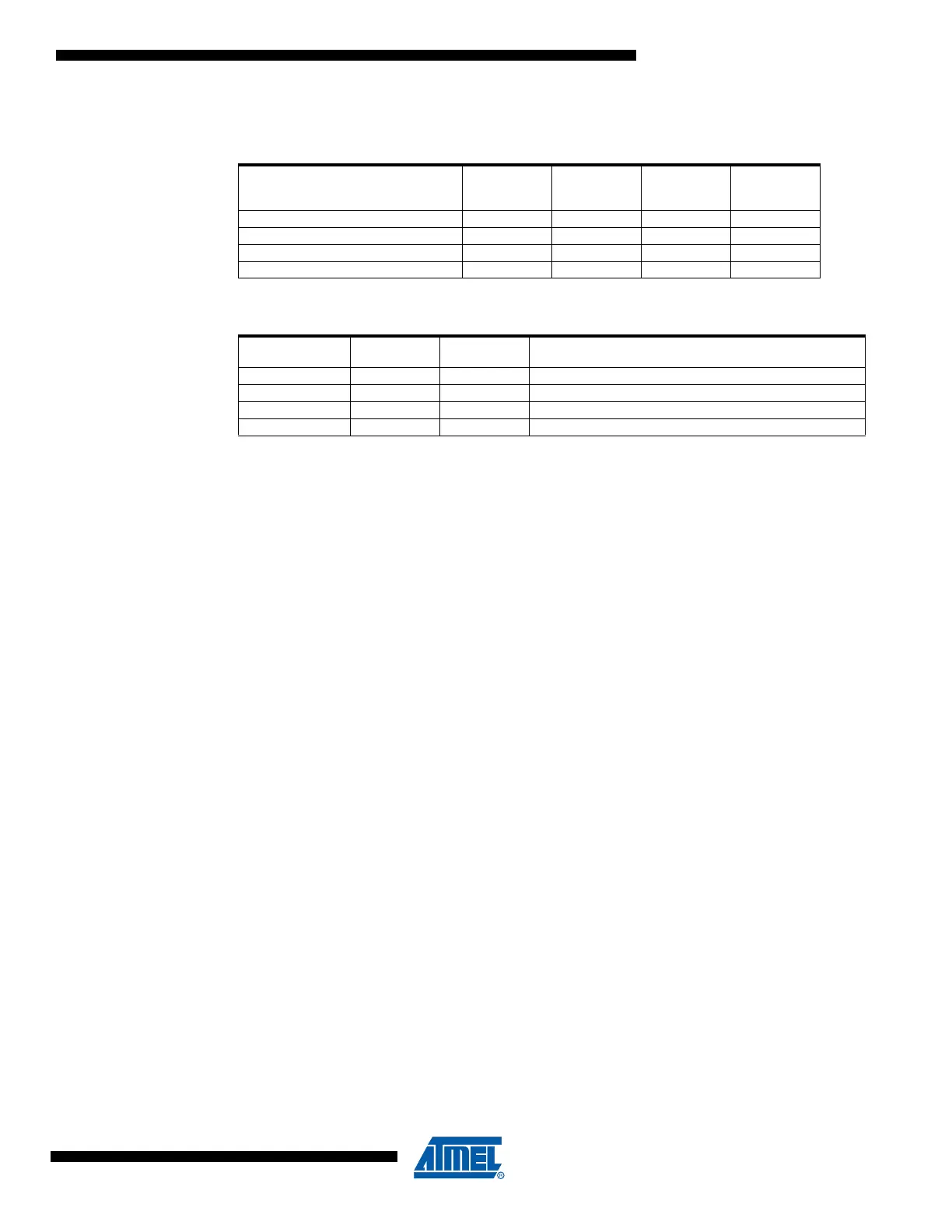
Let’s consider 4 sections in the Flash, described below:
Failing cases :
Problem fix / workaround
If protection level 3 is mandatory, the LPM instruction must be moved outside the failing
sections.
7. CAN acknowledge error in 3-sample mode with prescaler =1
Some acknowledge errors can occur when the clock prescaler = 1 (BRP[5..0] = 0 in
CANBTR1 register) and the SMP bit is set (CANBTR3[0] = 1 in CANBTR3 register). That
can result in a reduction of the maximum length of the CAN bus.
Problem fix / workaround
If BRP[5..0]=0 use SMP=0.
6. CAN transmission after 3-bit intermission
If a Transmit Message Object (MOb) is enabled while the CAN bus is busy with an on going
message, the transmitter will wait for the 3-bit intermission before starting its transmission.
This is in full agreement with the CAN recommendation.
If the transmitter lost arbitration against another node, two conditions can occur:
- At least one receive MOb of the chip are programmed to accept the incoming message. In
this case, the transmitter will wait for the next 3-bit intermission to retry its transmission.
- No receive MOb of the chip are programmed to accept the incoming message. In this case
the transmitter will wait for a 4-bit intermission to retry its transmission. In this case, any
other CAN nodes ready to transmit after a 3-bit intermission will start transmit before the
chip transmitter, even if their messages have lower priority IDs.
Problem fix / workaround
Always have a receive MOb enabled ready to accept any incoming messages. Thanks to
the implementation of the CAN interface, a receive MOb must be enable at latest, before the
1
st
bit of the DLC field. The receive MOb status register is written (RXOK if message OK)
immediately after the 6th bit of the End of Frame field. This will leave in CAN2.0A mode a
minimum 19-bit time delay to respond to the end of message interrupt (RXOK) and re-
enable the receive MOb before the start of the DLC field of the next incoming message. This
Table 33-1. Flash memory sections
Memory
space A :
Application
Memory
space B :
Application
Memory
space C :
Application
Memory
space D :
Bootloader
Bootsize=4096 Words 0000h-2FFFh 3000h-3FFFh 4000h-6FFFh 7000h-7FFFh
Bootsize=2048 Words 0000h-37FFh 3800h-3FFFh 4000h-77FFh 7800h-7FFFh
Bootsize=1024 Words 0000h-3BFFh 3C00h-3FFFh 4000h-7BFFh 7C00h-7FFFh
Bootsize=512 Words 0000h-3DFFh 3E00h-3FFFh 4000h-7DFFh 7E00h-7FFFh
From memory
space
To memeory
space
Bug comment
LPM instruction D B Allowed but should not be valid
LPM instruction B D Allowed but should not be valid
LPM instruction B A or C Not allowed but should be
LPM instruction A or C B Not allowed but should be

 Loading...


