HSP588
Use and maintenance manual pag. 25
4 Use and running
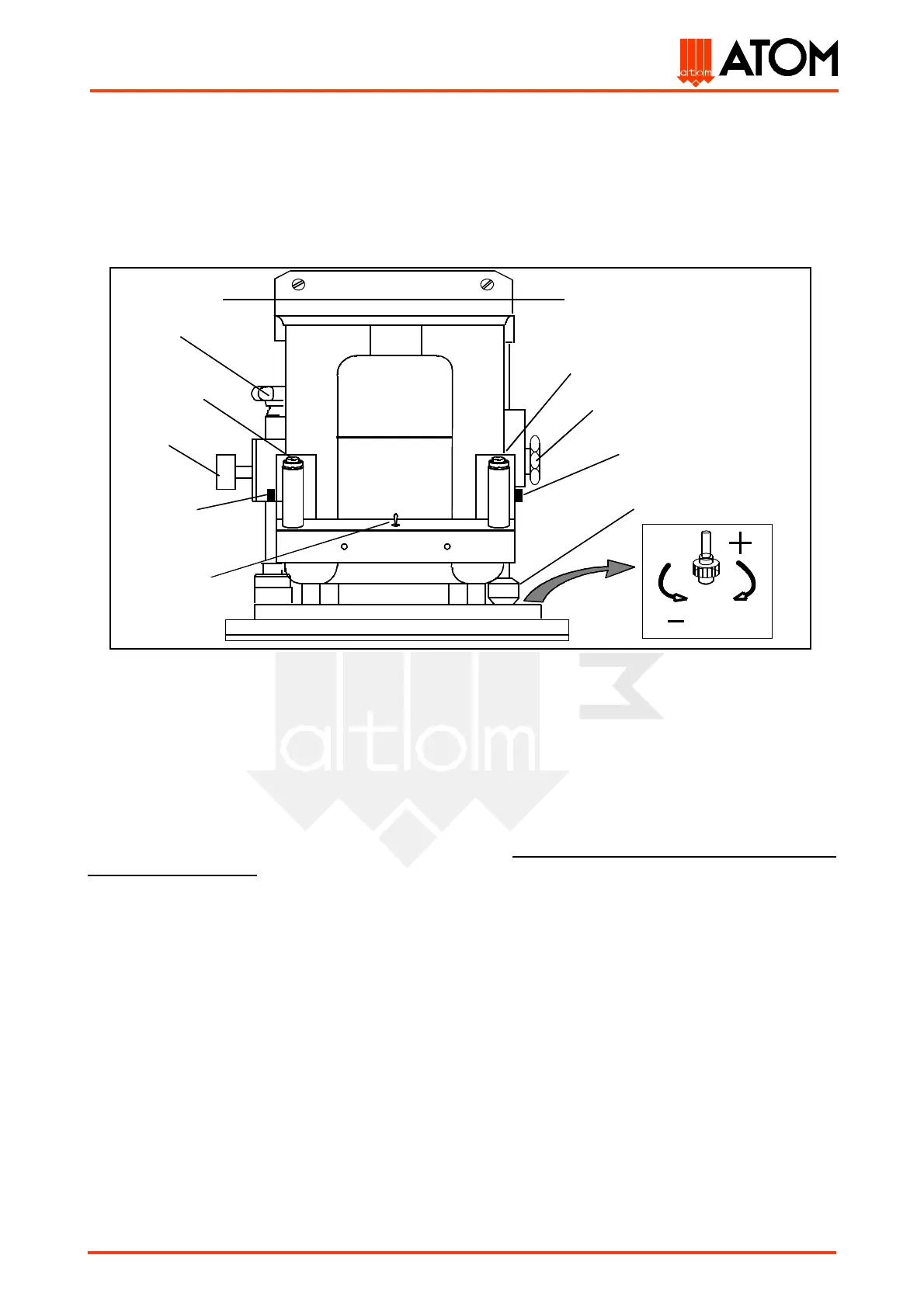
4.1 Control devices
On the travelling head are located the mechanical controls for the cutting stroke-end adjustment and for
the wished daylight between striking plate and cutting-die:
(G) selector which allows either to insert the operating cycle (AUTOMATIC) or to adjust the cutting stroke-
end (ADJUSTMENT);
(H) daylight adjusting hand-wheel: it locks the striking plate ascent in the wished position;
(I and L2) pushbutton for travelling head displacement from left to right;
(L1 and L2) synchronized cutting pushbuttons;
(M) screw for adjusting hand-wheel locking;
(N) cutting stroke-end positioning hand-wheel: it allows the striking plate stroke-end setting during
cutting (cutting stroke-end). By turning it counter clockwise, the stroke-end sets up on the correct cutting
height; by turning it clockwise the stroke-end value stores. Do not turn the hand-wheel during
cutting operation !
(O and L1) pushbutton for travelling head displacement from right to left;
(P) micro adjustment ring nut: it advances (counter clockwise rotation) or delays (clockwise rotation)
the cutting stroke-end, thus decreasing or increasing the cutting power;
(V) daylight adjusting lever: it locks the striking plate ascent in the wished position.
Fig. 1