HSP588
Use and maintenance manual pag. 38
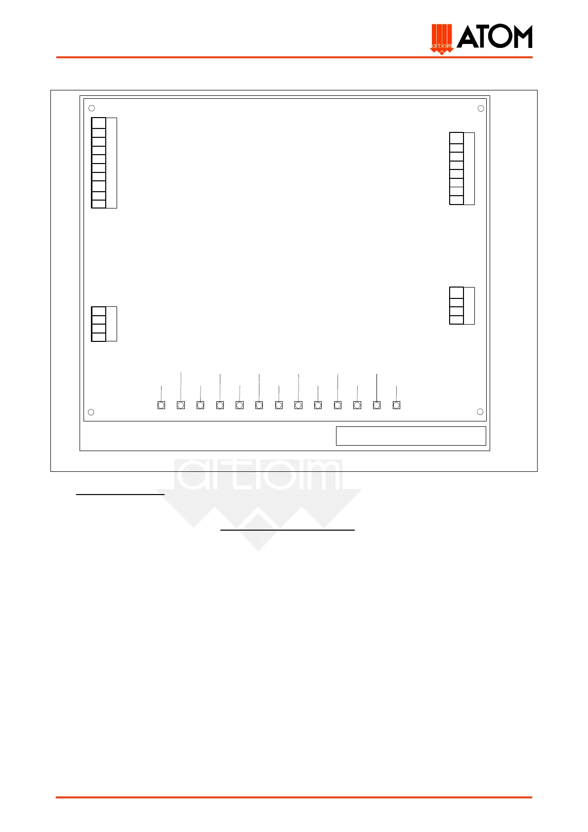
5.2 Printed circuit card description
The printed circuit card (code 02003100, table. 13), which controls all the machine functions, is located
inside the electrical equipment protecting cover (left side of the machine). To replace it, remove the cover
through the fixing screws, operate on the card fixing screws and take out the card from its connectors: the
whole operation must be carried out only when the machine is off!
As shown in the picture, there are 13 signalling leds on the printed circuit card which may be useful to
trace possible anomalies in the main electric devices of the machine: the operator will be able therefore to
verify these devices by checking the pertinent leds on the ground of the following list:
DL1) left pushbutton led: its lighting up indicates the functioning of the left cutting pushbutton (N.15);
DL2) right pushbutton led: its lighting up indicates the functioning of the right cutting pushbutton
(N.15);
DL3) left travelling head displacement led: this led lights up when pressing the pushbutton (N. 16) for
the manual translation of the travelling head to left;
DL4) right travelling head displacement led: this led lights up when pressing the pushbutton (N. 17) for
the manual translation of the travelling head to right;
DL5) ADJUSTMENT-AUTOMATIC switch led: this led lights up when the selector (N.14) is on AUTOMATIC
position;
DL6) controls feeding led: its lighting up indicates the feeding of the printed circuit card input circuits (it
must light up on switching on the machine);
DL7) integrated circuits leds: its lighting up indicates the feeding voltage in the integrated circuits of the
printed circuit card (it must light up when switching on the machine);
35
HSP 588 Printed circuit card
36
49
37
22
26
J1
Trolley connector
50
38
32
29
42
30
31
33
DL1
DL2
DL3
DL4
DL5
DL6
DL7
DL8
DL9
DL10
DL11
DL12
DL13
11
13
12
10
6
4
8
25
28
52
46
48
J2
Control panel connector
J3
Trolley stroke-end
J4
Feeding and electrovalves
outputs connector