Chapter 2
Overview APC100
Front panel APC100
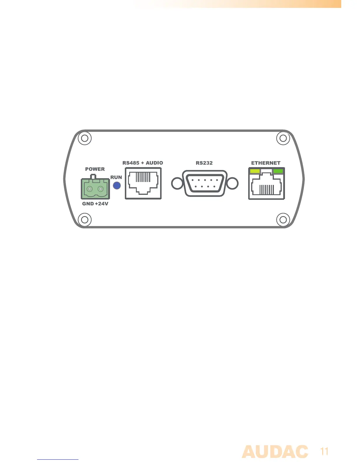
APC100 Front panel
Various control and configuration ports are located on the front panel of the APC100
together with the 24 Volts power connection.
1) 24 Volts power connector:
24 Volts DC mains power should be applied to this connector. Connect the wires of the
included power supply (PSD241) here. Mind the polarity markings when connecting
the power supply.
2) ‘RUN’ LED:
The blue ‘RUN’ LED will indicate the current operation mode of the device. When the
device is running in normal mode, this LED will blink with a constant frequency.
3) ‘RS485 + AUDIO’ RJ45 connector:
Connections to any controlling or configuring peripheral (wall panels, paging
microphones, ... ) or matrix system should be made on this databus. This databus
carries all audio and control signals between the APC100, peripheral interfaces and
matrix systems. Connections should be made using twisted pair CAT5E (when using
analogue audio transfer) or CAT6 (when using digital audio transfer) cabling.
This databus is implemented twice (once on front and once on rear panel), both
having identical possibilities and specifications.