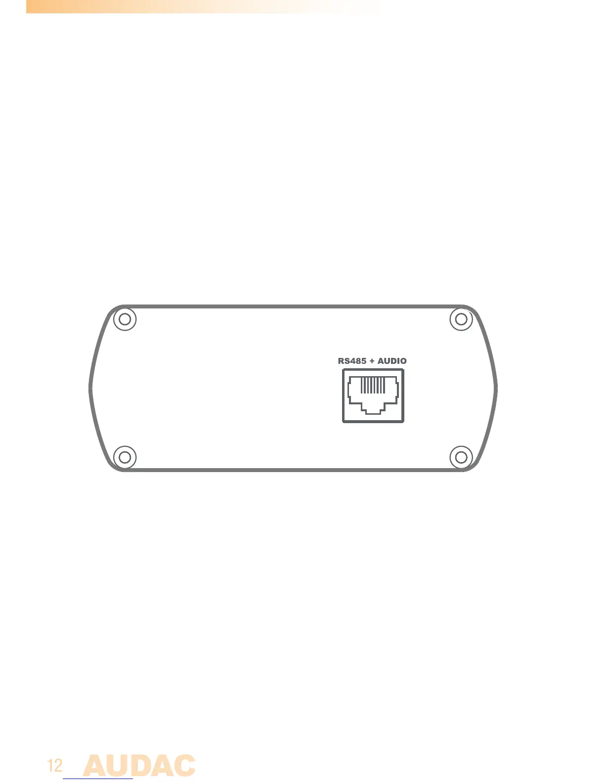
Rear panel APC100
APC100 Rear panel
‘RS485 + AUDIO’ RJ45 connector:
The rear panel of the APC100 contains only one databus connection. This databus
connection has identical possibilities and specifications as the databus connection
implemented on the front panel of the APC100. When a connection between the
APC100 and a peripheral interface or matrix system is made, the selection between
both connections can be freely chosen.
The additional advantage of the second implemented databus makes the APC100
applicable to a connection between a peripheral device (wall panel, paging
microphone, ... ) and a matrix system. In this typical application one databus
connection can be used as input while the second connection can be used as output.
4) RS-232 control port:
The RS-232 control port is implemented using a DB9 connector. Any communication
between the APC100 and external control hardware equipped with an RS-232 control
port can be made in this way. The pinout and communication protocol settings are
described in chapter 1 of this manual.
5) Ethernet connection:
The APC100 is equipped with an Ethernet network connection implemented using
an RJ45 connector. The green and orange LED’s will indicate whether the network
is connected and active. Using this port, the APC100 can be connected in any LAN
network.