Chapter 1
Connections and connectors
CONNECTION STANDARDS
The in- and output connections for AUDAC audio equipment are performed
corresponding to international wiring standards for professional audio equipment.
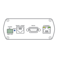
RS232 (serial connection interface):
For connection with home automation systems, or other remote control equipment
Connection Standard RS232
PIN 2 APC100 TX
PIN 3 APC100 RX
PIN 5 GND
Settings 19200 Baud
8 Bit
1 Stop bit
No parity
No Handshaking
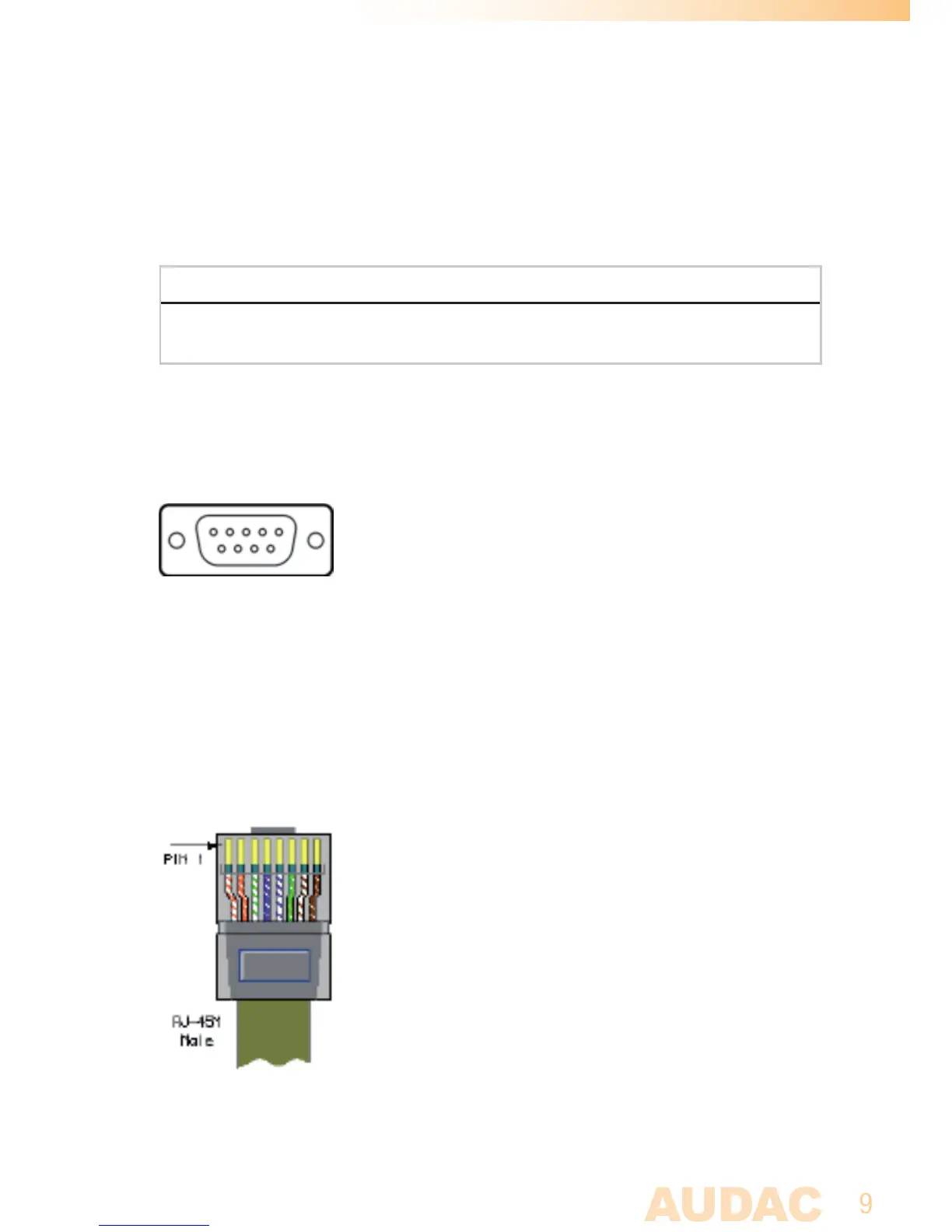
RJ45 (RS485, Audio, +24V DC):
For connection to matrix systems / peripheral devices
Pin 1 White-Orange AUDIO A
Pin 2 Orange AUDIO B
Pin 3 White-Green +24V DC
Pin 4 Blue RS485 A
Pin 5 White-Blue RS485 B
Pin 6 Green GND
Pin 7 White-Brown AUDIO A
Pin 8 Brown AUDIO B