35
FUNCTIONS AND COMMANDS
•
On / Stand-by
After the connection to the mains network, as described in the previous sections, it is
possible to commute the unit to the operating condition acting on the “ON” button (see
part 1, page 47).
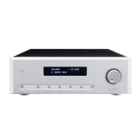
In fact, when pressing this button, the blue LOGO will turn on to a fixed light and the
display will show, for about four seconds, “AUDIA FLIGHT ONE” (fig. 1, page 45) and,
subsequently, on the first row, the volume level value (expressed in attenuation decibel)
and, on the second row, the selected input (fig. 2, page 45).
Remember that all settings remain stored only if the unit is powered by the main switch
(part. 20, page 47, position “1”), except for the data in the “set” menu (chapter
“ADVANCED FUNCTIONS” at page 16), that will stay stored even with no power.
You can use the remote control for this function.
•
Volume
The volume can be adjusted using the multi-functional knob (part. 10 at page 47) in
standard conditions, that is with no selected routine.
Moving the multi-functional knob to the right the volume will increase, moving it to the
left the volume will decrease (attenuation operative range from –90.0 dB to +10.0 dB,
with a 0.5 dB resolution).
You can use the remote control for this function.
Remark: Using the remote control, pressing the “+” or the “-” buttons, the change of the
level is actuated with 0.5 dB steps for the first four seconds and, subsequently, at 5 dB
steps in the range from –90.0 dB to –15.0 dB; from –15.0 dB to +10.0 dB the change is
always at 0.5 steps.
• Input selection
In standard conditions, namely with no selected routine, the second row of the display
(fig. 2 at page 45) will show the selected input.
A number will appear on the left-hand side of the second row of the display,
corresponding to the corresponding input on the back of the amplifier and, then, a string
of characters that the user can personalize (chapter “ADVANCED FUNCTIONS” par. “set
edit” at page 37) corresponding, in default conditions, to “INPUT” for the inputs “1”, “2”,
“3”, “4” and “INPUT BAL ” for the input “5”.
The position “6”, named on the display “INPUT A/V”, select the six inputs corresponding
to the “multi-channel” mode”.
To select one input you only have to press the “INPUT” button (part. 2 at page 47) and
use the multi-functional knob to select the required input.
You can check that the routine of the input selection is enabled by means of the “<INP”
indicator (fig. 3 at page 45) on the right-hand side of the second row of the display. The
input selection routine stays active as long as you act on the knob; 5 seconds after stop
acting on the knob, the inputs selection routine will automatically clear (the “<INP”
indicator on the display will disappear”).
You can use the remote control for this function.