Ports A, B, and C
Auxiliary Output Ports A, B, and C are independent 8-bit digital
control ports at separate DB9 connectors on the rear of the DCX-127.
The settings of the 8 bits may be controlled from the DCX software
panel or they may be swept over a range via the Sweep Panel. Settings
from the DCX software panel may be made as binary (mouse only),
octal, decimal, or hexadecimal numbers. The binary control and
display button-indicators are functionally in parallel with the
octal-decimal-hexadecimal field. Any change made to the binary
buttons is immediately reflected in the octal-decimal-hex field, and
vice-versa. To change a value using octal, decimal, or hex units, the
desired unit must first be selected (or the present unit accepted). A new
value may be entered into the field from the keyboard or the existing
value edited, followed by the
E key.
J 141 (Port D)
Connector J141 is an auxiliary output “Port D,” similar to Auxiliary
Output Ports A, B, and C. However, it also provides +5 V, +15 V, and
-15 V supplies. J141 is a DB-15 connector. You can control the J141
Port D with the following OLE command:
AP.DCX.PortDOutput
Table 5 shows the J141 connector pin assignments.
Operation Panel
DCX-127 Multifunction Module User’s Guide Page 27
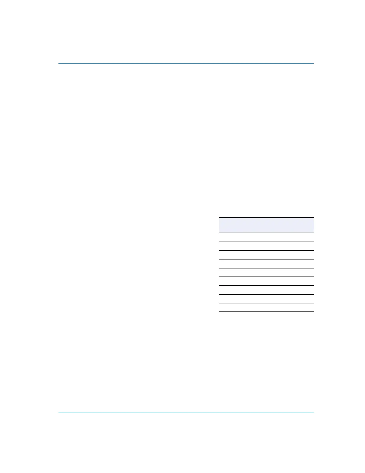
Pin
Number
Port A, B, & C
1 Bit 7 (MSB)
2 Bit 6
3 Bit 5
4 Bit 4
5 Bit 3
6 Bit 2
7 Bit 1
8 Bit 0 (LSB)
9 Ground
Table 4. Auxilliary Port A, B, and C Connector pin assignments