8
3. KEY MEM
To turn the processor on and off when the vehicle ignition is turned on / off.
Remark: This signal is memory-dependent: if the processor was turned off by a car sub-key connected to the
KEY MEM, it will turn on again by turning the ignition key. If the processor was turned off by a different method
(e.g. DRC) while the KEY MEM was still active, it will not turn on again through the KEY MEM and you will have to
turn it on through either the DRC or REM IN.
4. MUTE IN: To mute the bit Ten outputs when starting the engine by connecting the terminal to the starter turn-on
input or other devices. This control works by jumping the terminal to 12V.
Remark: The MUTE IN terminal can be used to enable the AUX IN input
(see 8.6.5)
. In this case the output mute function,
set by default, will be disabled.
5. DRC
DRC (Digital Remote Control) connection to configure the processor.
6.
USB
USB (type B) connection plug, to connect the processor to a PC and manage its functions through the bit Ten
software. The connection standard is USB 1.1 / 2.0 compatible.
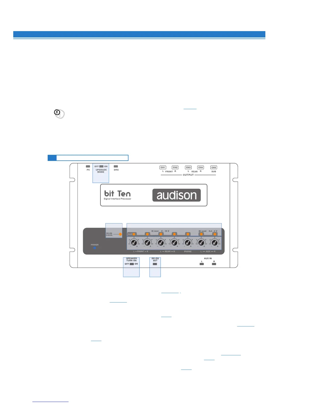
1. IN level: Input signals adjustments.
By turning the dials counter-clockwise, sensitivity decreases; by turning them clockwise, it increases.
This setting is important for an optimal signal / noise ratio (see 8.1 - 8.2).
2. CLIP: Input clipping detector (see 8.1 - 8.2).
If the LED lights up, it indicates clipping on the selected input.
3. DE-EQ CHECK: When lit, meaning comes from its state (see 8.1).
•LED ON: A de-equalization curve has been recorded.
• LED Flasching: You are performing a de-equalization analysis of the MASTER main input signal
(see 8.1 - 8.2).
4. DE-EQ SET: Button to begin analysis or de-equalization functions during system calibration
without using a PC (see 8.1).
5.
SPEAKER TURN ON:
Switch OFF does not allow turning the device on from the MASTER high-level main input (see 4.2.2 - 5.4).
Switch ON allows turning the device on from the MASTER high-level main input (see 5.4).
6.
UPGRADE MODE: Switch ON allows updating in RESCUE MODE (see 9.4), and the POWER LED will start flashing.
4.5 CONTROLS AND SETTINGS
6
4
5 4
2
1
3