AudioArts Lightning / June 2018
CONTROLS AND FUNCTIONS
page 2 – 9
Recording Calls
The Lightning has two USB ports. USB2 is designed to connect to a PC running
VoxPro, Audition, or other recording app. The Monitor panel has switches for selecting
the audio that goes to the computer. Turning on switch3 for USB 2 will send the audio
from the Callers to the left channel (switch1 must be off). Turning on switch 4 for USB2
will send a mono sum of the left and right channels of PGM4 (switch 2 must be off).
For example, if you want to record a conversation with Caller1, make sure that the
Caller2 fader is set to full off (∞) then adjust the Caller 1 fader for a good level on the
call recording app. Assign the Callers to any bus other than PGM 4 (for this example,
we will use PGM3). Assign your recording mic channel to the PGM4 bus, turn that
channel on and adjust the channel fader for a good record level. You will also need to
assign the mic channel to the same channel to which the callers are assigned (PGM3 in
this example) so that the callers can hear the mic. The caller will hear a mix-minus of
the bus to which it is assigned (PGM3). The callers will be recorded on the left channel
of the computer, and PGM 4 will be recorded on the right channel.
NOTE: The Caller Out 1 and 2 trim pot settings do not affect the Telco Record output
level.
TIP: To hear the caller, set Monitor dipswitch 1-2 to on to feed Cue into the console
headphones or turn off dipswitch 1-4 so stop the cue speaker from muting while a
mic is live.
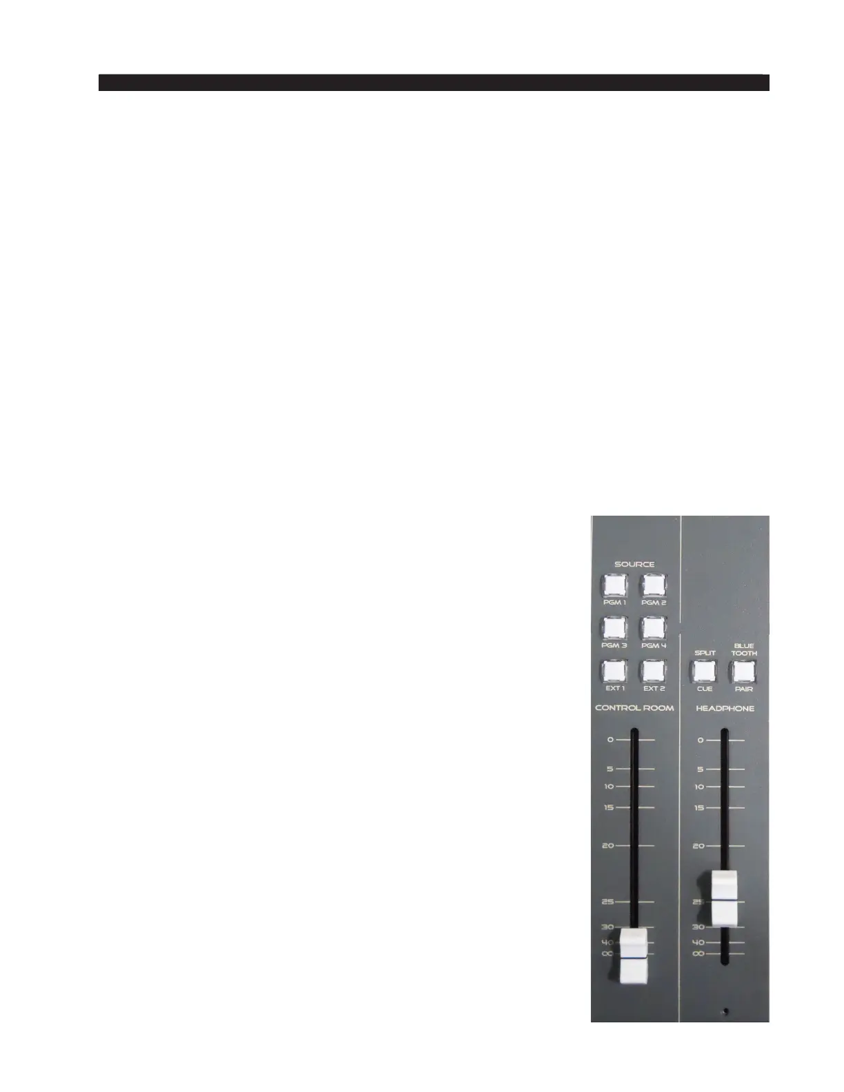
Control Room
This is the console operator’s monitor that allows the operator
to listen to the console’s four stereo Program outputs and two
external stereo line level inputs. This section of the console includes
the monitor level controls for the control room, headphone, and
cue circuits.
In a typical radio application the console is located in the
Control Room. Speakers in the Control Room allow the console
operator to listen to the console bus outputs to be assured that
the console is performing as desired. These speakers are fed by a
stereo signal from the console’s Control Room output. In addition
to the Control Room output, the operator may also desire to listen
to specic isolated faders via the cue system and the console’s
internal cue speaker, or may want to listen via headphones. Thus,
the control room monitor consists of the above mentioned level
controls, along with four program assign buttons, and an external
input buttons.
In some instances the console operator may also be performing
talent whose voice will be heard over the radio. The operator’s
microphone may thus provide a part of the signal that is going
out over the air. If that signal is the one being monitored with the
Control Room speakers, there is the potential for feedback. The
amplied signal from the Control Room speakers is picked up by
the microphone and amplied to a new, higher, level, which then
is once again picked up by the microphone. The signal quickly