page Appendix – 3
AudioArts Lightning / June 2018
APPENDICES
AudioArts Lightning / June 2019
• Turn off the power to the console.
• Remove the screws that hold the Input panel down,
and carefully remove the panel from the frame.
Caution: Ribbon cable will be plugged into the
panel.
• Place the Input panel face side down; remove the
three screws from the top of the PCB.
• Screw down three (440x3/16”Hex x 1/4”long)
standoffs into #1, #2 and #3 positions. Note that
fourth standoff (pos.#4) comes assembled on the
card.
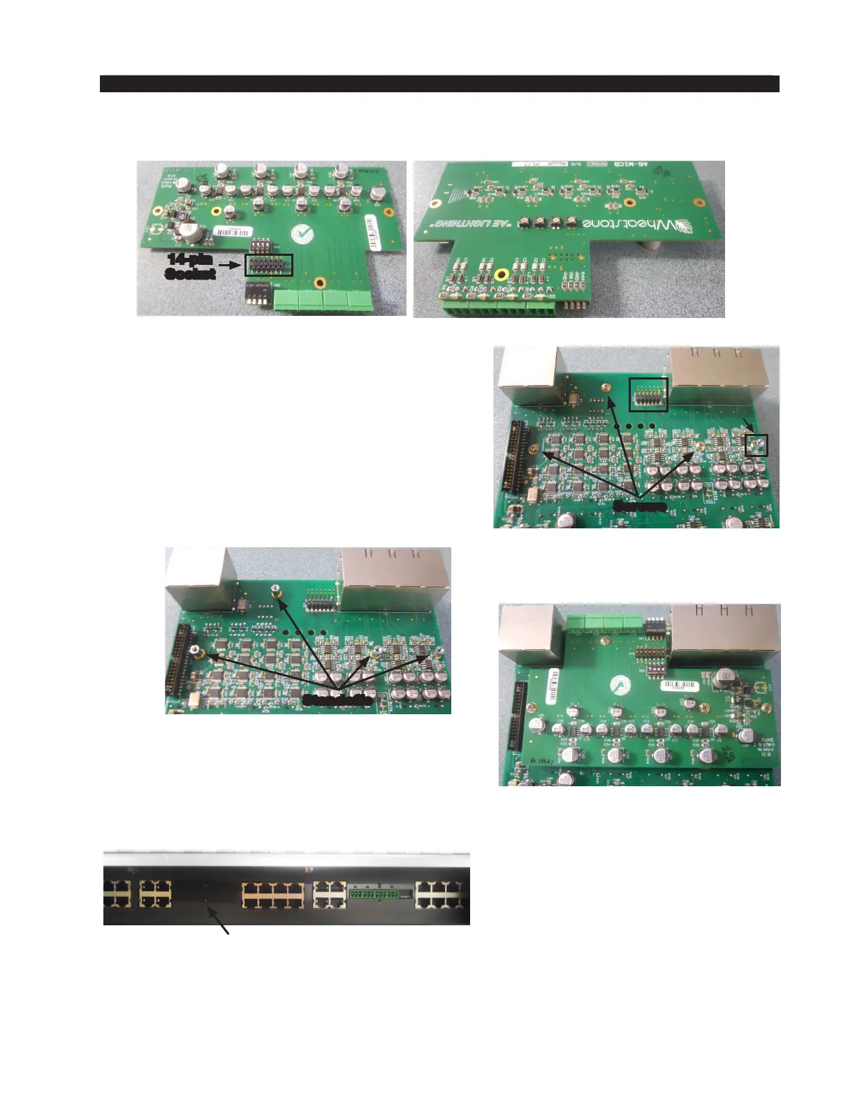
Installing the Additional Mic Preamp Card
14-pin
Socket
The additional Mic Preamp card comes complete with mounting hardware.
Perform the following steps to install the Mic Preamp card:
• Set appropriate dipswitches to enable Mic Preamp to Input A. See “Console Programming
Options” on page 2-15 for details.
• Re-install the removed Input panel.
This completes the Mic Preamp card installation procedure.
• Plug-in the Mic card’s 14-pin socket into the Input
panel’s 14-pin header and screw down three pre-
viously removed screws, and one supplied screw
(440x3/16 Phillips panhead) to secure the Mic
Preamp card.
• Remove the metal plate from the rear of console
to get access to Mic’s connectors.
Input Panel with Mic Preamp Card Installed
Standoffs
Metal Plate
Input Panel
#1
#2
#3
#4
Screws