8
9
Installation Manual
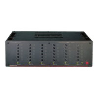
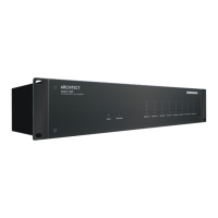
Model 2660
ARCHITECT
™
Getting Started
1. Turn o power to all com-
ponents before making any
connections.
2. When making connections, des-
ignate red RCA plugs as right, and
designate white, black, or grey plugs
as left. This is a good idea for all sig-
nal connections made in your audio
system. The key is consistency. Stick
with the same color coding and you’ll
reduce possible problems.
3. Whenever possible, keep power
cords away from signal cables to pre-
vent induced hum. This is especially
important if you bundle the cables to
keep the installation neat looking.
4. Use quality interconnect cables. We
know from experience that really
cheap cables can cause a multitude
of problems. They tend to break
inside or corrode, causing a loss of
signal or hum. They also have poor
shielding.
5. If you need to run the RCA audio
cables more than 20 feet, consider
using an active balanced line driver
for the signals. This will provide
better noise rejection against nasty
things like hum, spikes, local talk
radio, and metaphysical paranormal
phenomena, etc. The AudioControl
balanced line driver components
(BLD-10, BLR-10 and BLX-10) are an
excellent way to send audio over long
distances with standard Cat-5 wiring.
Check them out at audiocontrol.com.
6. If you are using the Bus A digital
input, and running higher resolution
sample rates (96 kHz - 192 kHz), use
high-quality interconnect cables.
Getting Started
Installation Examples
Home Installation
Commercial Installation
BUS A local local local local
Room Zones
Multiple Sources
Background Speakers
One Source Only
Whole House
Audio System
Controller
BUS A BUS A BUS A
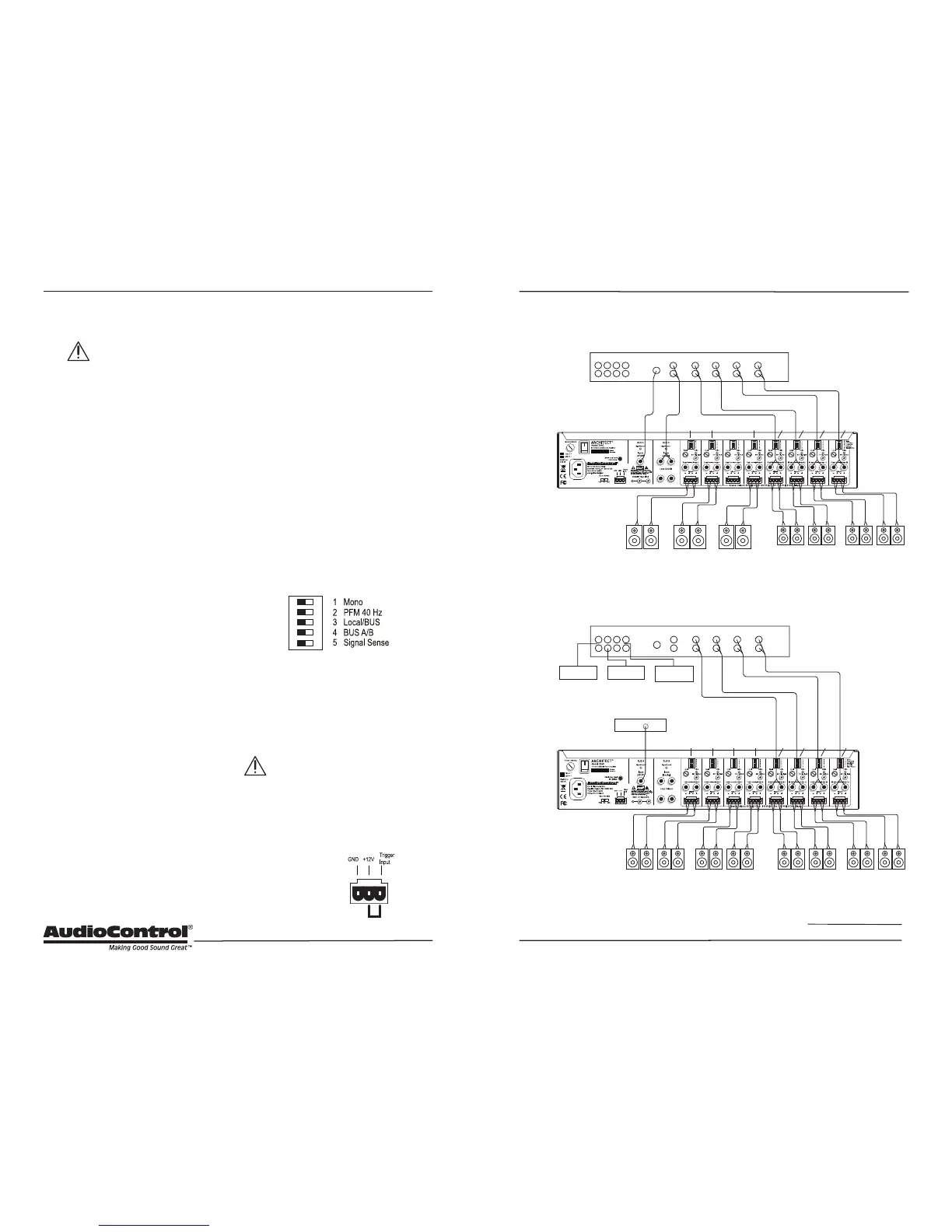
Installation Examples
The next page shows two examples of
typical Architect Model 2660 installations.
The rst example is a home installation
with four separate zones, each playing a
dierent local analog source. Two other
zones are playing the Bus B analog source,
and one is playing the Bus A digital source.
The second example is a bar or restaurant
installation where multiple speakers in the
main seating area are playing the Bus A
digital source, and separate room zones
are playing individual local analog sources.
The versatile DIP switches of each zone
allow the selection of the local inputs, BUS
A input, and BUS B input to play in that
zone.
An Important Note about Triggering
The Architect Model 2660 master trigger
connectors (two TS 1/8” and a 3-pin block)
are used to turn on the unit or place it into
standby mode.
If no trigger voltage is present at
any of these trigger inputs, then
the unit will be in standby, with all
zones muted. If you are not using master
triggering, then you must install a short
wire link from the 12V output pin to the
trigger input pin of the 3-pin connector.
To put the unit into
standby, remove the
link.
Wire Link
 Loading...