7. Electrical connection
.
Work on the electrical system or equipment must only be
carried out by a skilled electrician himself or by specially
instructed personnel under the control and supervision of
such an electrician and in accordance with the applicable
electrical engineering rules.
.
Installation regulations for Modbus must be observed for
the wiring.
(For literature references, please refer to appendix C)
Make sure to respect electromagnetic compatibility (EMC) when installing
cables:
Signal and bus cables are susceptible to interference.
Electric power cables are interference sources.
.
Lay cables being susceptible to inferference or sources of interference at
the highest possible distance from each other.
.
The interference immunity of signal and bus cables increases if the cables
are laid close to the ground potential.
.
Avoid long cables, if possible, or make sure that they are laid in locations
with low susceptibility to interference.
.
Avoid long parallel paths with cables being either interference sources or
susceptible to interference.
7.1 Power supply (standard) For explosion-proof version (type designation: AMExB/ AMExC), please
refer to page 15 or page 17.
.
Check whether type of current, supply voltage, and frequency comply with
motor data (refer to name plate at motor).
.
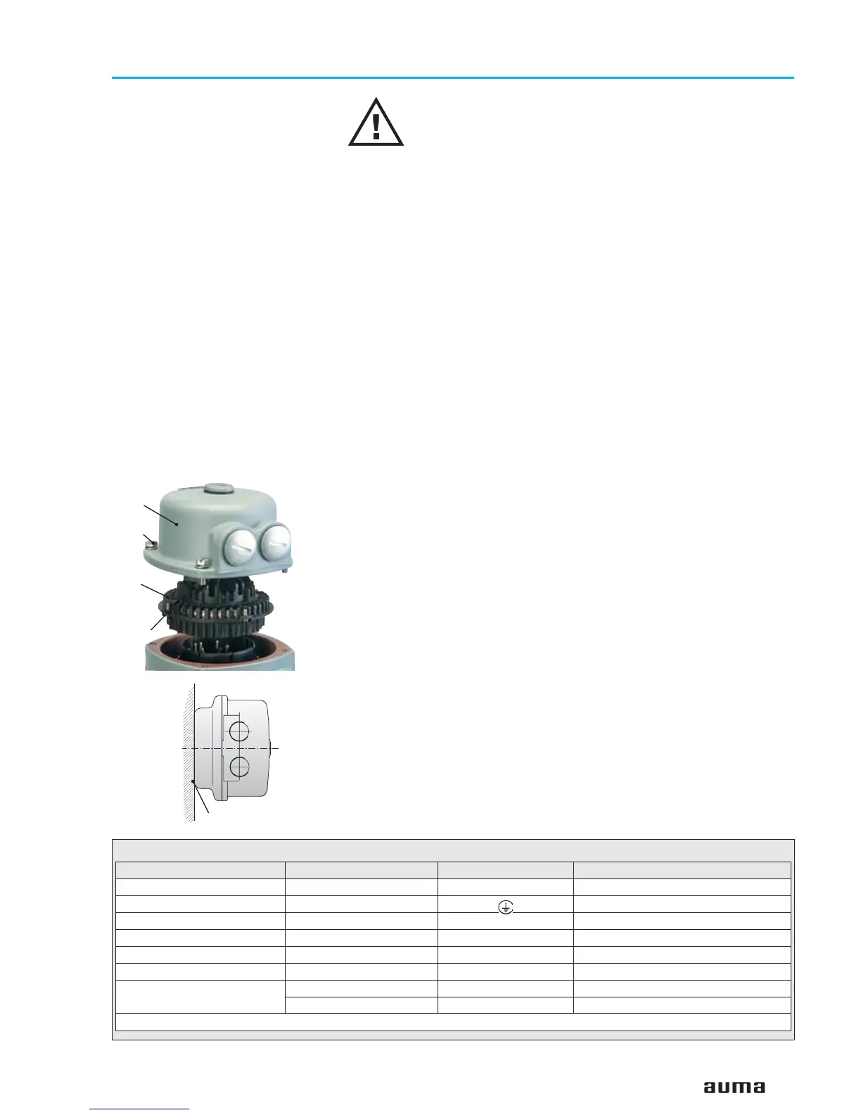
Loosen bolts (50.01) (figure B-1) and remove connection housing.
.
Loosen screws (51.01) and remove socket carrier (51.0) from plug cover
(50.0).
.
Insert cable glands suitable for connecting cables.
(The enclosure protection stated on the name plate is only ensured if suit-
able cable glands are used).
.
Seal cable entries which are not used with suitable plugs.
.
Connect cables according to order-related wiring diagram.
The wiring diagram applicable to the actuator is attached to the
handwheel in a weather-proof bag, together with the operation instruc-
tions. In case the wiring diagram is not available, it can be obtained from
AUMA (state commission no., refer to name plate) or downloaded directly
from the Internet (www.auma.com).
A special parking frame (figure B-2) for protection against touching the bare
contacts and against environmental influences, in case the electrical
connection has been removed, is available.
11
Actuator controls AUMA MATIC AM/ AMExB/ AMExC
Operation instructions Modbus
Figure B-1: Connection
50.0
50.01
51.0
51.01
Parking frame
Technical data Motor power connections
1)
Protective earth Control terminals
No. of contacts max. 6 (3 are used) 1 (leading contact) 50 pins / sockets
Marking U1, V1, W1, U2, V2, W2 1 to 50
Connecting voltage max. 750 V – 250 V
Nominal current max. 25 A –
16 A
Type of customer connection Screws Screw for ring lug Screws
Cross section max. 6 mm
2
6 mm
2
2.5 mm
2
Material: Pin/ socket carrier Polyamide
Polyamide Polyamide
Contacts Brass (Ms)
Brass (Ms)
Brass, tin plated or gold plated (option)
1)Suitable for copper wires. For aluminium wires, please contact AUMA
Table 2: Technical data AUMA plug/ socket connector for bus connection
Figure B-2: Parking frame (accessory)
 Loading...