X11 Second analogue input (analogue 3/4)
An external 0/4 – 20mA sensor for transmitting the measured values via the
Modbus can be connected to this input.
If switch S1.1 is set to position ON, then pin 5 (AN 3/4+) is connected to
GND and input AN 3/4– can be used in the same way as AN 2.
If the switch is set to position OFF, a differential measurement between AN
3/4+ and AN 3/4– can be performed.
X12 First analogue input (analogue 2).
An external 0/4 – 20mA sensor for transmitting the measured values via the
Modbus can be connected to this input.
.
Potential-free differential measurement is not possible due
to the presence of a permanent ground (GND) connection.
.
For these signals, proposed external wiring diagrams
(appendix B) must be observed.
.
The inputs AN2, AN3, and AN4 do not have galvanic isola-
tion via opto-isolator. The maximum load of the 24 V DC
voltage source applied by the sensors must not exceed
40 mA altogether.
14.3 Modbus connection assignment
X8 MODBUS The bus signals and the galvanically isolated power supply for the bus termi-
nation are allocated to this plug.
14.4 Assignment positioner connections
X10 The signals required for the position transmitter with potentiometer or with
RWG are allocated to this plug.
46
Actuator controls AUMA MATIC AM/ AMExB/ AMExC
Modbus Operation instructions
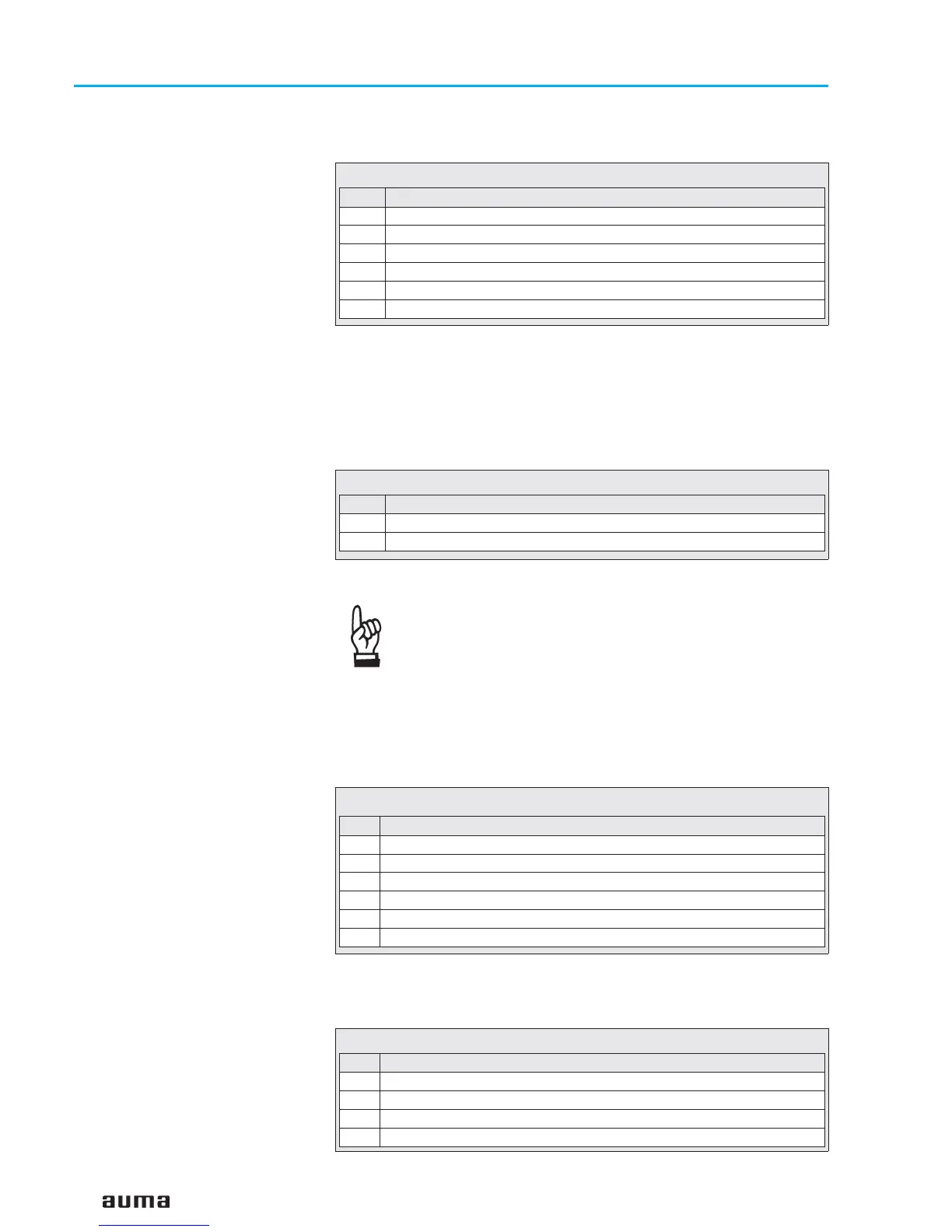
Pin Description
1 + 24 V DC
2 GND (system ground)
3 GND (system ground)
4 AN 3+: analogue signal 0 – 20 mA (plus)
5 AN 4–: analog signal 0 – 20 mA (minus)
6 GND (system ground)
Table 7: Analogue inputs at plug X11
Pin Description
1 AN 2: analogue signal (0 – 20 mA)
2 GND (system ground)
Table 8: Analogue inputs at plug X12 AI 2
Pin Description
1 Channel 1: B cable Modbus
2 Channel 1: A cable Modbus
3 Channel 2: A cable Modbus (redundant channel)
4 Channel 2: B cable Modbus (redundant channel)
5 GND float (Modbus ground)
6 + 5 V float (Modbus + 5 V)
Table 9: Assignment for plug X8
Pin Description
1 + 5 V for potentiometer
2 AN 1: analogue signal from position transmitter
3 GND (system ground)
4 + 24V for RWG
Table 10: Assignment for plug X10 AI 1
 Loading...