15.2 Position feedback does not function
.
Check if the voltage at plug (X1) on the Modbus board, pin 3 (-) and pin 2
(+) is subject ot linear incrementation when running open and linear
decrement when running close.
The value for position CLOSED should be within the range of 0 to 2 V.
The value for position OPEN should be within the range of 3 to 5 V. The
voltage difference between CLOSED and OPEN should be superior to 3V.
15.3 Actuator is not switched off by the limit switch in direction CLOSE
The actuator is set to torque seating.
Set actuator to limit seating:
.
Set switch S4 (see figure H, page 44) on the Modbus board to position
‘LIMIT’.
.
Adjust switch S1-2 on the logic board (see page 47) to position 1.
15.4 Actuator stops immediately after having started
.
Set switch S2-2 (blinker transmitter) on the logic board to position ‘ON’.
15.5 Actuator does not signal reference operation, connection failure position transmitter or signal
interruption position transmitter
The position transmitter (potentiometer, RWG) is faulty.
.
Check position transmitter wiring and connection
.
Check the setting of parameter 1 “Position transmitter”
.
If the actuator is not equipped with a position transmitter, parameter 1 has
to be set to value 0 (no position transmitter)
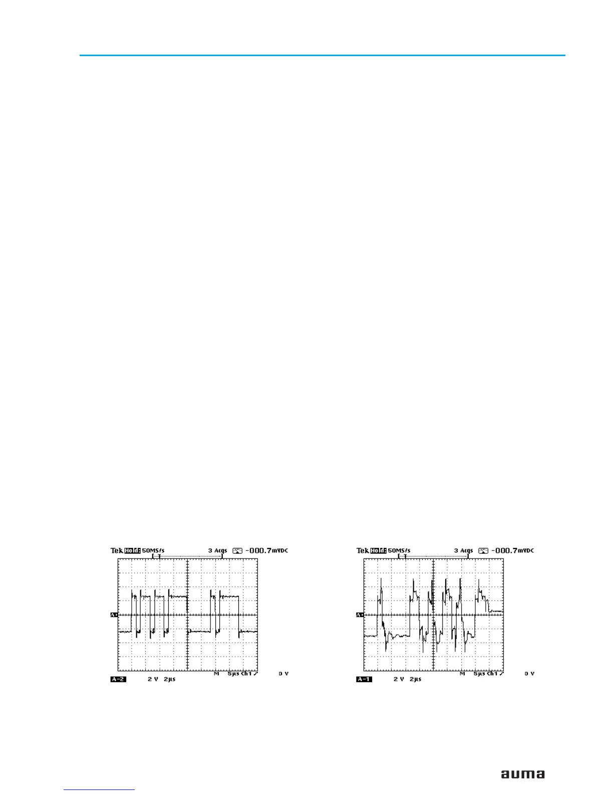
15.6 Measuring the Modbus signals using an oscilloscope
On the Modbus board, the signal from Modbus channel 1 on the plug (X8
Modbus, refer to page 46) pin 1 (P/B) and pin 2 (N/A) can be checked using
a digital oscilloscope.
The off-load voltage between pin 1 (+) and pin 2 (-) must be positive and
within the range of 0.8 V and 1.4 V.
51
Actuator controls AUMA MATIC AM/ AMExB/ AMExC
Operation instructions Modbus
Example for correct Modbus signal: Example for incorrect Modbus signal
(Bus only terminated on one side):
 Loading...