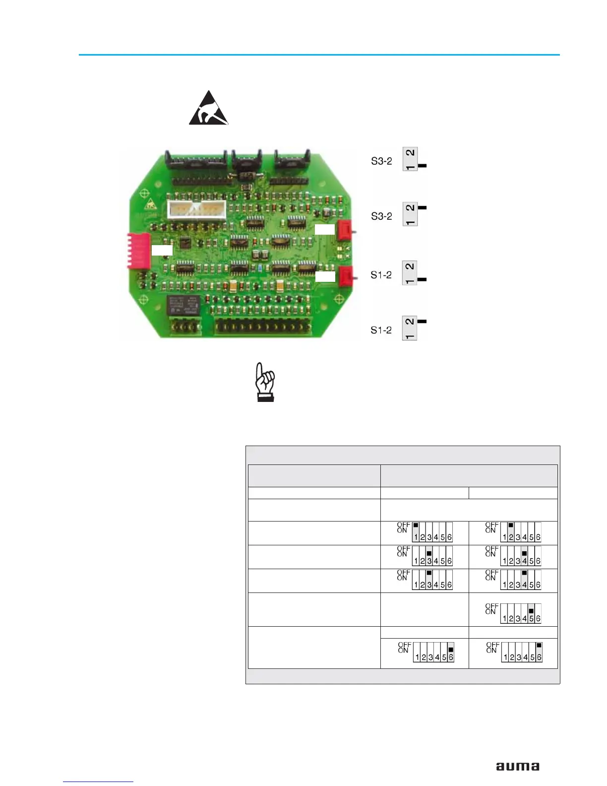
14.5 Checking/ setting the switches on the logic board
The settings on the logic board are already made in the factory, according to
the order details.
The logic board is located below the Modbus board.
The setting of the end position seating in end position
CLOSED must be the same on the Modbus board (LED 0 in
default mode, figure J, page 44) and on the logic board
(switch S1-2).
47
Actuator controls AUMA MATIC AM/ AMExB/ AMExC
Operation instructions Modbus
S3-2:
Switching-off in end position OPEN.
Switch position has no influence.
When controlling via Profibus DP,
switching-off is always realised by
limit seating in end position OPEN
Position 1:
Switching-off by limit seating in end
position CLOSED
Position 2:
Switching-off by torque seating in
end position CLOSED
S3-2
S1-2
S2-2
Figure K: Logic board
DIP switch S2-2 Programming
(ON = pressed)
Direction CLOSE
Direction OPEN
Self-retaining REMOTE
Self-retaining REMOTE
may not be used!
Push-to-run operation REMOTE
Self-retaining LOCAL
Push-to-run operation LOCAL
Blinker transmitter (option)
Blinker transmitter
must be deactivated!
Blinker transm. deact.
Torque error: torque switch tripping
(in mid-travel) contained in collec-
tive fault signal (insignificant for
fieldbus interface)
included not included
Table 11
 Loading...