Register 9: Second analogue input (wiring diagram designation analogue 3/4)
The data content depends on parameter 25 (coding analogue 3/4), holding
register offset: 0x4018 (hexadecimal), 16408 (decimal)
Settings:
0: 0 to 100 percent (default value)
1: 1 to 1000 per mil
2: 0 to 1023 (raw value of analogue-digital converter, not standardised)
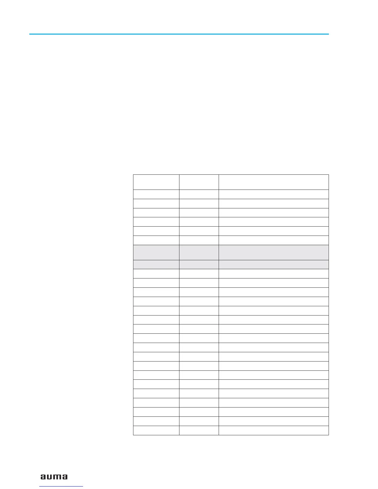
9.3 Reading the feedback signals from the actuator using status functions
Functions to be used:
Read Input Status (02)
Grey bits are collective signals. They contain the results of a disjunction (OR
operation) of other information.
30
Actuator controls AUMA MATIC AM/ AMExB/ AMExC
Modbus Operation instructions
Offset
(hexadecimal)
Offset
(decimal)
Content
(Description in subclause 9.2)
0x2000 8192 OPEN position
0x2001 8193 CLOSED position
0x2002 8194 Setpoint reached
0x2003 8195 - -
0x2004 8196 Running OPEN
0x2005 8197 Running CLOSE
0x2006 8198
Warning signals
(refer to page 28, register 5)
0x2007 8199 Error signals (refer to page 27, register 4)
0x2008 8200 Thermal fault
0x2009 8201 Mains failure (phase loss)
0x200A 8202 Selector switch REMOTE
0x200B 8203 Selector switch LOCAL
0x200C 8204 LSO (WOEL)
0x200D 8205 LSC (WSR)
0x200E 8206 TSO (DOEL)
0x200F 8207 TSC (DSR)
0x2010 8208 Wrong command
0x2011 8209 Selector switch not remote
0x2012 8210 Thermal fault
0x2013 8211 Mains failure (phase loss)
0x2014 8212 TSO (DOEL) fault
0x2015 8213 TSC (DSR) fault
0x2016 8214 - -
0x2017 8215 - -
0x2018 8216 24 V power supply failure
0x2019 8217 Channel 2 active
 Loading...