7.10 Bus cables Only cables according to the recommendations of EIA 485 standard may be
used for Modbus wiring.
A maximum of up to 32 Modbus devices may be connected in one segment.
If more stations are to be connected to one Modbus network, several
segments must be connected with repeaters.
The bus cable must be laid at a distance of at least 20 cm from other cables.
It should be laid in a separate, conductive, and earthed cable trunking.
It must be ensured that there are no potential differences between the indi-
vidual devices on the Modbus (perform a potential compensation).
The max. cable length without repeater amounts to 1,200 m (independent of
the baud rate).
Cable recommendation for Modbus
Characteristic impedance: 35 to 165 Ohm, at a measurement
frequency of 3 to 20 MHz.
Cable capacity: < 30 pF per metre
Core diameter > 0.64 mm
Core cross section: > 0.34 mm², corresponds to AWG 22
Loop resistance: < 110 Ohm per km
Screening: copper shielding braid or shielding braid and
shielding foil
19
Actuator controls AUMA MATIC AM/ AMExB/ AMExC
Operation instructions Modbus
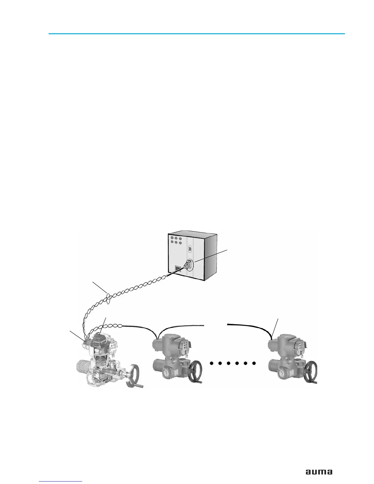
Figure F: Example: Modbus with one secment
Bus termination
switched on
Bus termination
switched on
Modbus board
AUMA MATIC
Modbus
Connection
board
2-wire cable
Controls (master)
 Loading...