14. Description Modbus interface
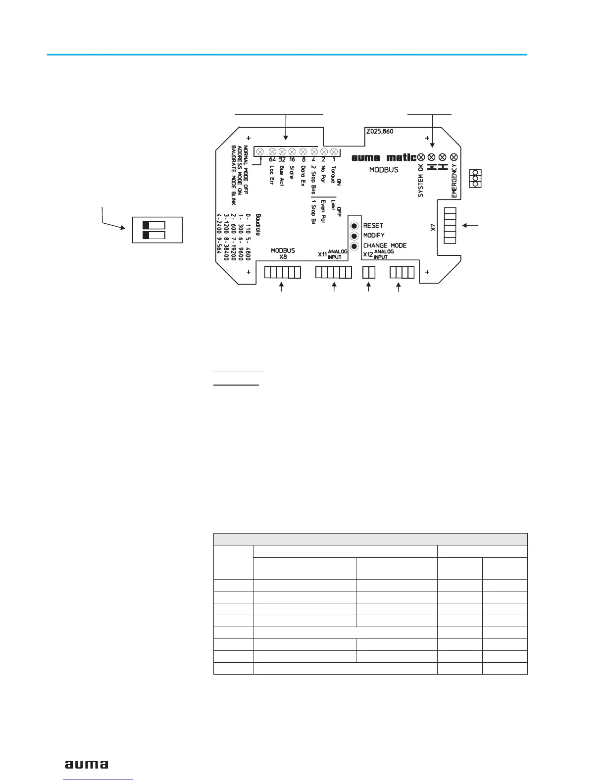
S1.1 When using the external analogue input X11 AI 3/4, the switch S1.1 must be
in position On.
S1.2 Switch for setting the position feedback via position transmitter potentiom-
eters/ RWG (option).
S1.2 = OFF:
The actuator is equipped with a potentiometer.
S1.2 = ON:
Switch may only be in this position if an RWG (0/4 – 20 mA) is
installed in the actuator.
14.1 Indication during system start-up
When starting the system, the LEDs 0 to 7 will be illuminated. LEDs L1 to L4
are switched off. This signifies that the board is correctly started.
After a short time (approx. 1/4 s), the LED L1 (round red LED) will be illumi-
nated and the LEDs 0 to LED 7 will be switched off one after the other. This
means that the microcontroller is now operating. If LED L1 is switched off
and the LEDs 0 to 7 are still illuminated, then the system is in the reset
status (this situation can also be reproduced by constantly pressing push
button T1).
14.1.1 Indications of operation LEDs 7 to 0
LED 0 Indicates torque or limit switching in end position CLOSED
(illuminated for torque switching)
LED 1 Indicates the quantity of the parity bits from the Modbus protocol
(illuminated for No Parity). Only No Parity and Even Parity are
supported, Odd paritiy is not supported
44
Actuator controls AUMA MATIC AM/ AMExB/ AMExC
Modbus Operation instructions
1
1
1
2
1
1
1
6
6
64
Figure J: Modbus interface board
X7
X8 Modbus X11 X12 X10
Switch S1
(below cover plate)
Taster
T1
T2
T3
LEDs: 7 6 5 4 3 2 1 0 L1 L2 L3 L4
Indications of operation
LED Default Mode Significance
LED on LED is off
Address
Mode
Baud rate
Mode
0 (red) torque seating limit seating
11
1 (red) no parity even parity
22
2 (red) 2 stop bits 1 stop bit
44
3 (red) data exchange no data exchange
88
4 (red) state (blinking)
16 –
5 (red) bus active no bus active
32 –
6 (red) local error no local error
64 –
7 (red) off
on blinking
 Loading...