16
Actuator controls AUMA MATIC AM/ AMExB/ AMExC
Modbus Operation instructions
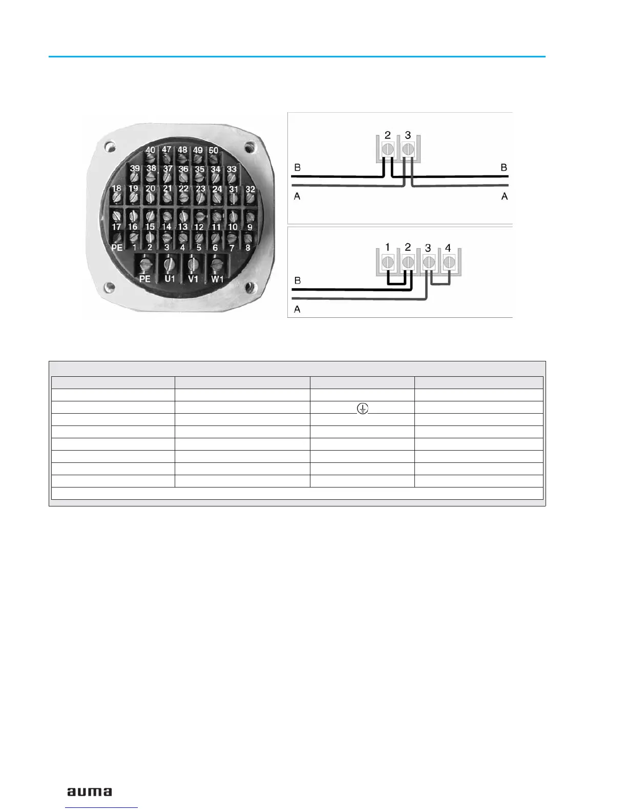
Figure D-3: Bus connection for channel 1 (standard)
Another bus device follows the actuator
Actuator is final bus device
from previous
Modbus device
channel 1
to next
Modbus device
channel 1
Technical data Motor power connections
1)
Protective earth Control terminals
No. of contacts max. 3 1 (leading contact) 38 pins/ sockets
Marking U1, V1, W1 1 to 24, 31 to 50
Connecting voltage max. 550 V – 250 V
Nominal current max. 25 A – 10 A
Type of customer connection Screws Screws Screws
Cross section max. 6 mm
2
6 mm
2
1.5 mm
2
Material: Pin/ socket carrier Araldite/ Polyamide Araldite/ Polyamide Araldite/ Polyamide
Contacts Brass (Ms) Brass (Ms) Brass (Ms) tin-plated
1)Suitable for copper wires. For aluminium wires, please contact AUMA
Table 5: Technical data Ex plug/ socket connector with terminal board for explosion-proof actuators
 Loading...