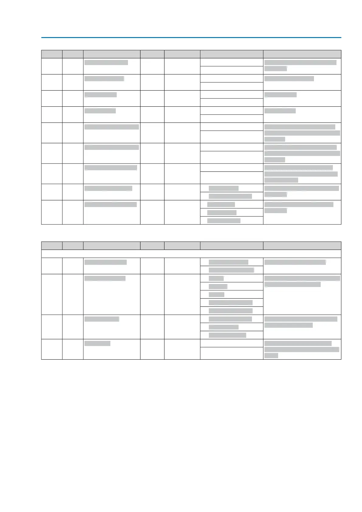
ExplanationSetting valueDefaultAccessParametersTypeNo.
Internal setpoint 2 for process
controller
Min = 0 [0.1 %]500R/W
Internal setpoint 2
U1667-5
Max = 1000 [0.1 %]
Proportional gain Kp
Min = 1 [0.1]10R/W
Proport. gain Kp
U1667-6
Max = 100 [0.1]
Reset time Ti
Min = 1 [s]1000R/W
Reset time Ti
U1667-7
Max = 1000 [s]
Rate time Td
Min = 0 [s]0R/W
Rate time Td
U1667-8
Max = 100 [s]
Minimum reaction required of
actual process value within reac-
tion time
Min = 0 [0.1 %]0R/W
Min reaction act. value
U1667-9
Min = 100 [0.1 %]
Maximum reaction required of
actual process value within reac-
tion time
Min = 100 [0.1 %]1000R/W
Max reaction act. value
U1667-10
Max = 1000 [0.1 %]
Reaction time for monitoring
min. or max. reaction of actual
process value
Min = 0 [s]0R/W
React. time act. value
U1667-11
Max = 100 [s]
Actual value source of process
controller
0 : I/O interface
0R/W
Actual value source
enum67-12
1 : Fieldbus interface
Modulating behaviour of PID
controller
0: P controller
0R/W
Modulating behaviour
enum67-13
1: PI controller
2: PID controller
Table 57: Failure behaviour
ExplanationSetting valueDefaultAccessParametersTypeNo.
Data length = 12 bytes
Activate failure behaviour0 : Good signal first
1R/W
Failure behaviour
enum15-1
1 : Immediately active
Setting the actuator reaction for
active failure behaviour
0 : STOP
0R/W
Failure operation
enum15-2
1 : CLOSE
2 : OPEN
3 : Approach position
4 : Execute last CMD
Failure source (failure reason)
for failure behaviour
1 : Fieldbus interface
4R/W
Failure source
enum15-3
2 : I/O interface
4 : Active interface
Failure operation is only ex-
ecuted after delay time has ex-
pired.
Min = 0 [0.1 s]30R/W
Delay time
Mmss0115-4
Max = 1800 [0.1 s]
67
Actuator controls
AC 01.2/ACExC 01.2 Profibus DP Appendix