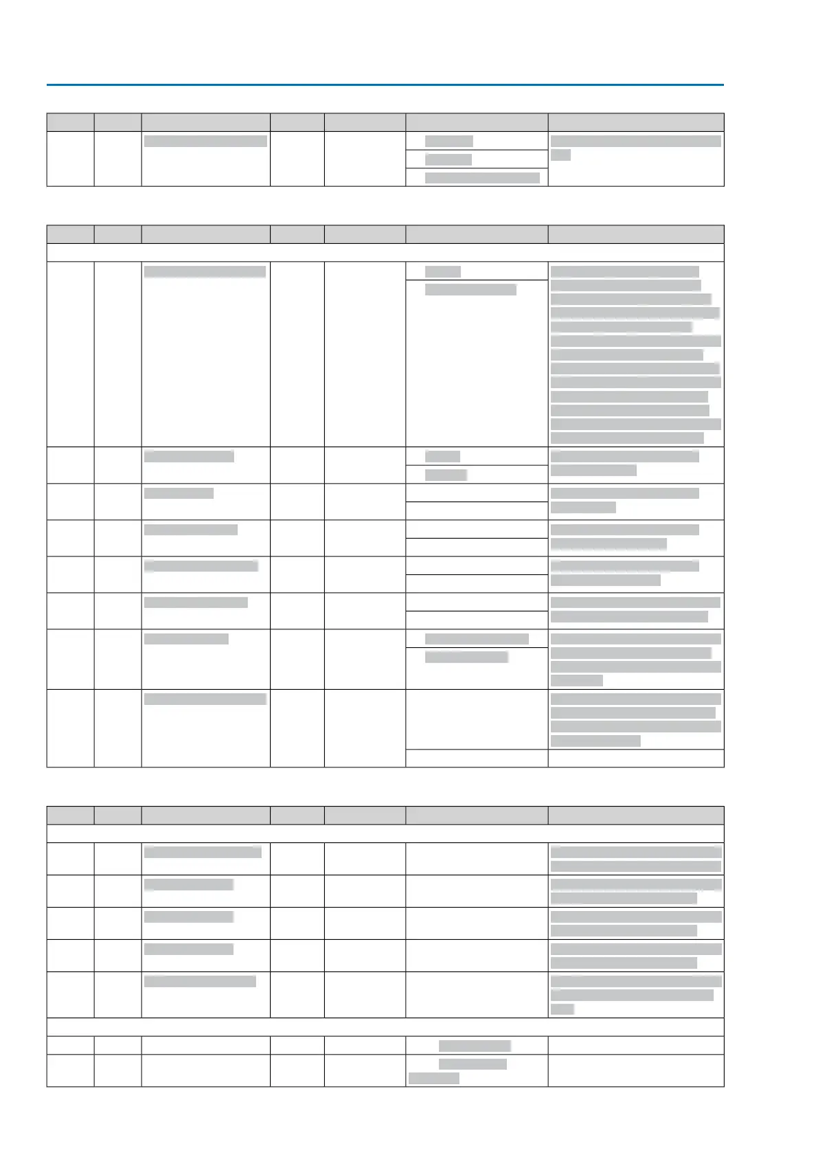
ExplanationSetting valueDefaultAccessParametersTypeNo.
Failure source of interlock func-
tion
1 : Interface
3R/W
Interlock failure source
enum27-4
2 : Fieldbus
3 : Active comm. source
Table 65: PVST
ExplanationSetting valueDefaultAccessParametersTypeNo.
Data length = 16 bytes
Setting the operation mode
PVST: Stroke = stroke-con-
trolled PVST; based on travel
across a defined stroke (stroke
PVST) within a given time
(PVST monitoring time); can be
started in any valve position
(even outside the end position)
End position test = PVST based
on test when leaving the end
position within a defined time
(PVST travel time); Can only be
started from an end position
0 : Stroke
0R/W
PVST operation mode
enum66-1
1 : End position test
PVST (Partial Valve Stroke
Test) behaviour
0 : OPEN
1R/W
PVST behaviour
enum66-2
1 : CLOSE
PVST (Partial Valve Stroke
Test) stroke
Min = 0 [0.1 %]100R/W
PVST stroke
U1666-3
Max = 1000 [0.1 %]
PVST (Partial Valve Stroke
Test) monitoring time
Min = 10 [0.1 s]600R/W
PVST monitoring
Mmss0166-4
Max = 3000 [0.1 s]
PVST (Partial Valve Stroke
Test) operating time
Min = 1 [0.1 s]20R/W
PVST operating time
Mmss0166-5
Max = 600 [0.1 s]
Waiting time during PVST prior
to returning to initial position.
Min = 1 [0.1 s]20R/W
PVST reverse time
Mmss0166-6
Max = 600 [0.1 s]
When function is active, a mes-
sage is generated if no PVST
can be executed during remind-
er period.
0 : Function not active
0R/W
PVST reminder
enum66-7
1 : Function active
Reminder period of PVST func-
tion. Generates message if no
PVST was executed during this
reminder period.
Min = 00R/W
PVST reminder period
U1666-8
Max = 65535
Table 66: Local controls
ExplanationSetting valueDefaultAccessParametersTypeNo.
Data length = 22 bytes
Signal assignment for indication
light 1 (left) on the local controls
370R/W
Indication light 1 (left)
enum28-1
Signal assignment for indication
light 2 on the local controls
269R/W
Indication light 2
enum28-2
Signal assignment for indication
light 3 on the local controls
270R/W
Indication light 3
enum28-3
Signal assignment for indication
light 4 on the local controls
268R/W
Indication light 4
enum28-4
Signal assignment for indication
light 5 (right) on the local con-
trols
369R/W
Indicat. light 5 (right)
enum28-5
Setting values for parameter no.: 28-1/-2/-3/-4/-5
372 : Not assigned
259 : End position
CLOSED
72
Actuator controls
Appendix AC 01.2/ACExC 01.2 Profibus DP