Byte 2: Actuator signals
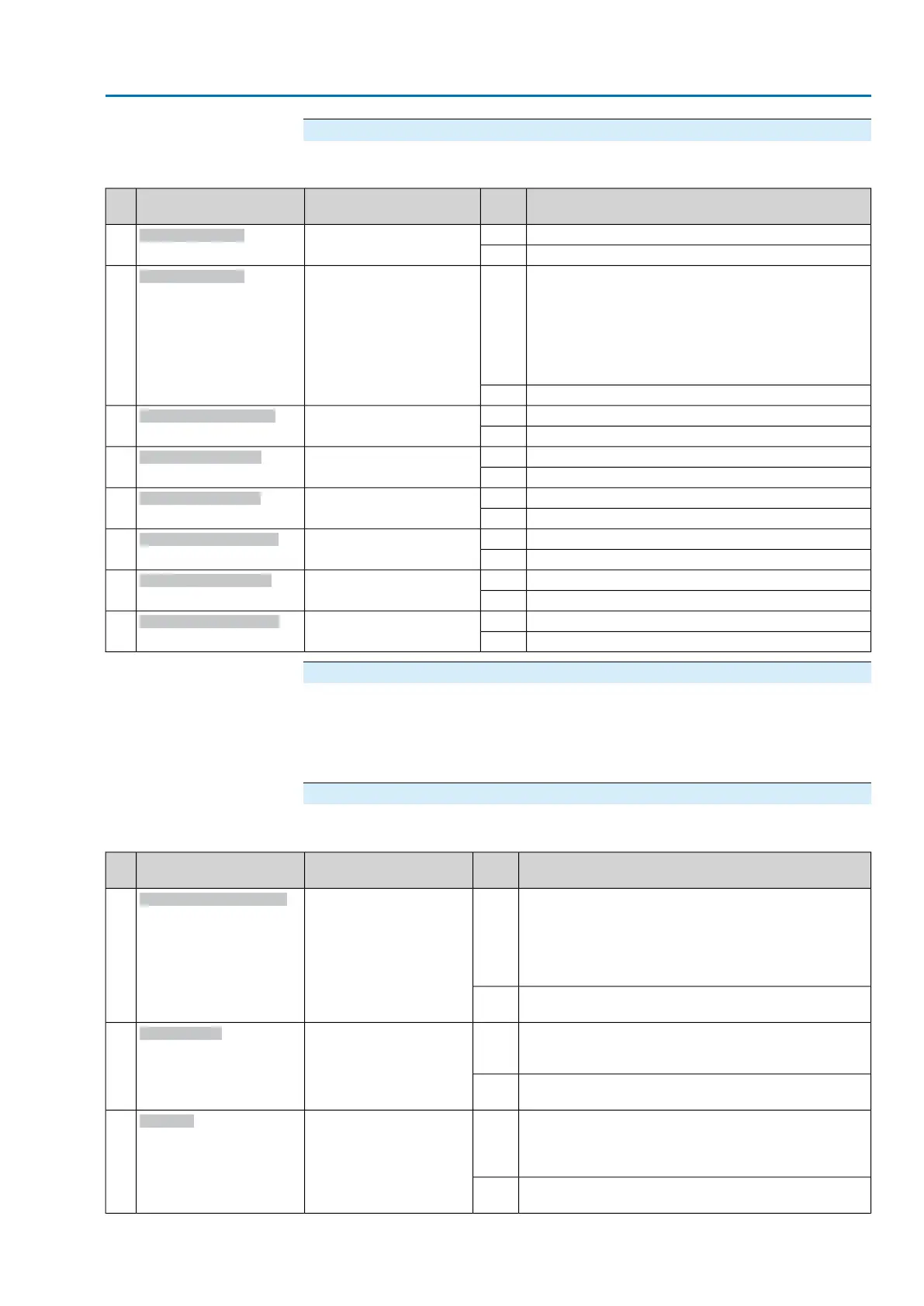
Table 5: Byte 2: Actuator signals
DescriptionValuePrm-Text-Def GSD fileDesignation
(process representation)
Bit
Motor protection tripped1(56) = "Bit: Thermal fault"
Bit: Thermal fault
0
No signal0
●
When connecting to a 3-ph AC system and with in-
ternal 24 V DC supply of the electronics: Phase 2 is
missing.
●
When connecting to a 3-ph or 1-ph AC system and
with external 24 V DC supply of the electronics: One
of the phases L1, L2 or L3 is missing.
1(57) = "Bit: Phase fault"
Bit: Phase failure
1
All phases are available.0
Selector switch is in position REMOTE.1(9) = "Bit: Sel. sw. RE-
MOTE"
Bit: Sel. sw. REMOTE
2
Selector switch is not in position REMOTE.0
Selector switch is in position LOCAL.1(8) = "Bit: Selector sw.
LOCAL"
Bit: Sel. sw. LOCAL
3
Selector switch is not in position LOCAL.0
Limit switch operated in end position OPEN1(12) = "Bit: Limit sw. OPEN"
Bit: Limit sw. OPEN
4
No signal0
Limit switch operated in end position CLOSED1(11) = "Bit: Limit sw.
CLOSED"
Bit: Limit sw. CLOSED
5
No signal0
Torque switch operated in direction OPEN.1(14) = "Bit: Torque sw.
OPEN"
Bit: Torque sw.OPEN
6
No signal0
Torque switch operated in direction CLOSE.1(13) = "Bit: Torque sw.
CLOSE"
Bit: Torque sw.CLOSE
7
No signal0
Bytes 3 and 4: Actual position
Byte 3 = high byte, byte 4 = low byte.
If a position transmitter (potentiometer, RWG, EWG, or MWG) is installed in the
actuator, bytes 3 and 4 are used to transmit the current actuator position.The value
is transmitted in per mil (value: 0 – 1,000).
Byte 5: Device status
Table 6: Byte 5: Device status
DescriptionValuePrm-Text-Def GSD fileDesignation
(process representation)
Bit
Collective signal 04:
Contains the result of a disjunction (OR-operation) of all
bits comprised in bytes 13 and 14 (Not ready REMOTE
1 and Not ready REMOTE 2).
The actuator cannot be operated from REMOTE.
The actuator can only be operated via the local controls.
1(22) = "Bit: Not ready RE-
MOTE"
Bit: Not ready REMOTE
0
In bytes 13 and 14, no signals are active (all bits are set
to 0).
0
Collective signal 02:
Contains the result of a disjunction (OR-operation) of all
bits of bytes 17 to 20 (Warning 1 to Warning 4).
1(21) = "Bit: Warnings"
Bit: Warnings
1
In bytes 17 and 20, no warnings are active (all bits are
set to 0).
0
Collective signal 03:
Contains the result of a disjunction (OR-operation) of all
bits of bytes 15 and 16 (Fault 1 and Fault 2).
The actuator cannot be operated.
1(20) = "Bit: Fault"
Bit: Fault
2
In bytes 15 and 16, no faults are active (all bits are set to
0).
0
23
Actuator controls
AC 01.2/ACExC 01.2 Profibus DP Description of the data interface