5. Description of the Profibus DP board
The Profibus DP boards is directly located below the local controls.
Figure 6: Profibus DP board
Hazardous voltage!
Risk of electric shock.
→
When connected to the mains, the local controls may only be removed by suitably
qualified personnel (electricians).
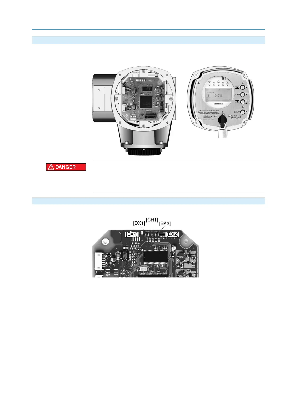
5.1. Indications (indication and diagnostic LEDs)
Figure 7: Indication and diagnostic LEDs
[BA2] Profibus channel 2 active (green)
[DX1] Data Exchange channel 1 (yellow)
[BA1] Profibus channel 1 active (green)
[CH1] Communication via channels 1/2 (yellow)
[DX2] Data Exchange channel 2 (yellow)
[BA2]
Option for redundancy
Illuminated in green if Profibus channel 2 is active.
[DX1]
If the LED is illuminated in yellow, the Profibus DP interface has entered the ‘Data
Exchange’ state on channel 1. Controlling the actuator by the Profibus DP master
and reading the actuator status can be performed in this state only.
[BA1]
Illuminated in green if Profibus channel 1 is active.
[CH1]
Option for redundancy
ON (illuminated in yellow): Communication via channel 1
51
Actuator controls
AC 01.2/ACExC 01.2 Profibus DP Description of the Profibus DP board