OFF: Communication via channel 2
[DX2]
Option for redundancy
If the LED is illuminated in yellow, the Profibus DP interface has entered the ‘Data
Exchange’ state on channel 2. Controlling the actuator by the Profibus DP master
and reading the actuator status can be performed in this state only.
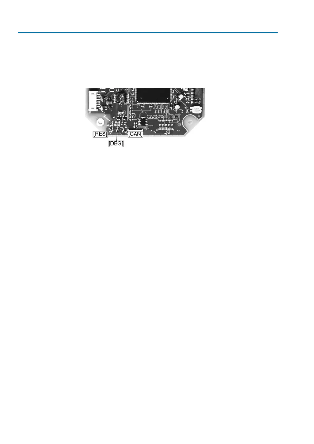
Figure 8: Status LEDs
[RES] RESET (green)
[DBG]DEBUG (green)
[CAN]CAN (red)
[RES]
Illuminated in green after Reset phase: 3.3 V voltage supply is ok.
[DBG]
Blinking in green after Reset phase: 5 V voltage supply is ok
Blinking at 1 Hz: PCB test
Blinking at 2 Hz: Application is ok.
[CAN]
Illuminated in red: Communication to logic is faulty.
Not illuminated: Communication with logic is ok.
52
Actuator controls
Description of the Profibus DP board AC 01.2/ACExC 01.2 Profibus DP