The value is transmitted in per mil (value: 0 – 1,000).
Bytes 15 to 26: Reserve
The contents are reserved for future extensions.
4.3. Profibus DP V1 services
— Option —
Apart from the cyclic DP-V0 process data exchange, the Profibus DP-V1 services
can establish an additional acyclic communication via the fieldbus.
Actuator controls with activated Profibus DP-V1 services grant access to the contents
of the device ID, the operating data, and the most important parameters for setting
and the maintenance information.
Access to the data of all actuators connected by the Profibus DP network is therefore
enabled for preventive maintenance or uniform parameter setting.
Actuator controls support an acyclic DP-V1 connection with controls (DPM1 = master
of class 1) and one acyclic DP-V1 connection with engineering stations (DPM2 =
master of class 2).
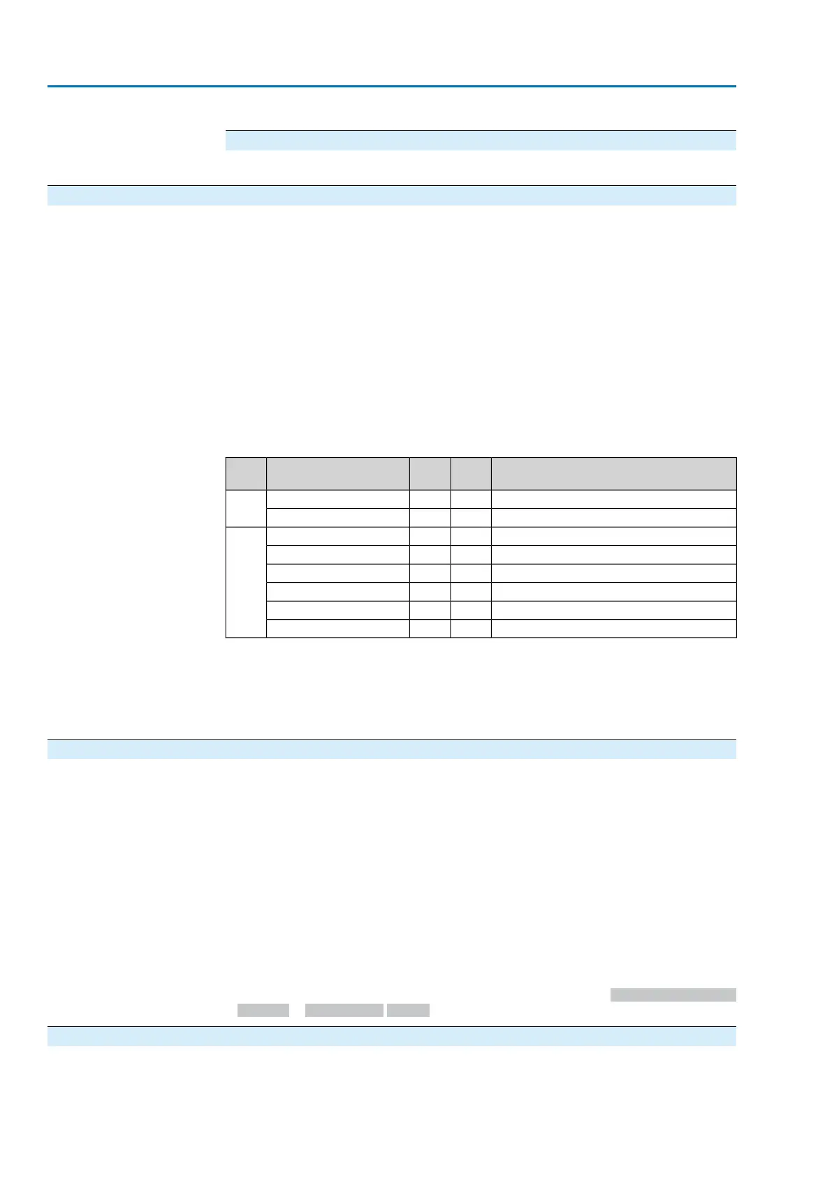
The following DP-V1 fault indications are supported:
CauseError
code
Error
class
Fault ind.
An invalid slot was accessed.211Access.Invalid SlotRead
An invalid index was accessed.011Access.Invalid Index
An invalid slot was accessed.211Access.Invalid SlotWrite
An invalid index was accessed.011Access.Invalid Index
The transmitted data length is invalid.111Access.write length
Invalid parameter value811Access.invalid parameter
No write access permitted611Access.access denied
Slot/index can only be read.110Application write error
Depending on the DCS, either a DTM (Device Type Manager) or an EDD (Electronic
Device Description) is required to integrate device-specific information, data and
parameters, which can be accessed via Profibus DP-V1, into the engineering station.
The availability of the Profibus DP-V1 services is preset in the factory. For a
description of the DP-V1 services, refer to the appendix.
4.4. Redundancy
— Option —
To increase the security of the installation, the actuator controls may be equipped
with a redundant Profibus DP interface.
The following redundant operation modes are supported:
1. Redundant behaviour according to AUMA redundancy (AUMA redundancy I or
AUMA redundancy II)
(use of AUMA 0C4F.GSD in combination with the ident. no. of the standard
version: 0x0C4F)
2. Redundant behaviour according to Profibus DP-V2 redundancy in accordance
with PNO guideline 2.212 (system redundancy or flying redundancy)
(use of AUMA AUMA 0CBD.GSD in combination with the ident. no. of the
standard version: 0x0CBD)
The redundant behaviour is set using the following parameter: Device configuration
> Profibus > Redundancy M0601
4.4.1. Redundant behaviour according to AUMA redundancy
This redundancy type can be selected if the DCS does not support Profibus DP-V2
redundancy according to Profibus DP guideline 2.212 but a redundant structure is
nevertheless required.
40
Actuator controls
Description of the data interface AC 01.2/ACExC 01.2 Profibus DP