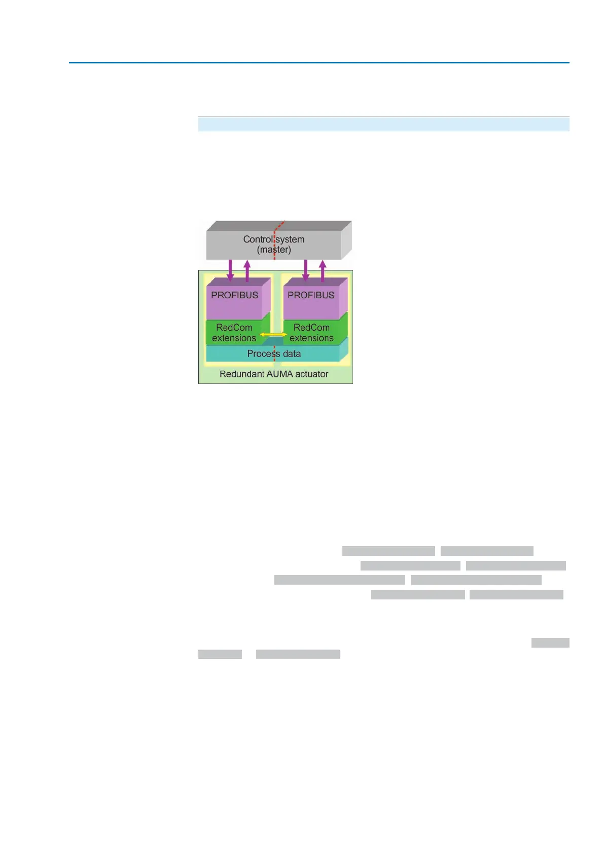
The physical structure of the redundant Profibus DP interfaces within the controls is
based on two independent, galvanically isolated Profibus DP interfaces with an
internal RedCom data channel for exchanging the communication status.
AUMA redundancy I
In general, the actuator decides autonomously which of the Profibus DP
communication channels will be the active channel and therefore be able to operate
the actuator and which channel will be the passive channel only providing feedback
signals of the actuator. The slave addresses can be individually assigned for
both channels.
Figure 1: Basic structure for AUMA redundancy I
The operation of both communication channels is logically, physically and
chronologically separated.
The communication channel, which first exchanges process data with the controls
(data exchange state), is the active channel, the second channel will automatically
become the passive channel.The actuator can only be controlled via the active
channel.
Controls (DPM1 = master of class 1) can only write and read acyclic data via the
active channel. Engineering stations (DPM2 = master of class 2) can use both
channels to read and write acyclic DP-V1 data (writing the same parameter via both
communication channels simultaneously is, however, not possible).
Byte 31 Fieldbus status is used to signal the following communication states of the
two channels to the DCS:
●
Active or passive channel (Bit: Channel 1 active, Bit: Channel 2 active)
●
Profibus DP Watchdog Status (Bit: Channel 1 DataEx, Bit: Channel 2 DataEx)
●
Fault state (Bit: Chan 1 FailState fieldbus, Bit: Chan 2 FailState fieldbus)
●
Available fieldbus communication (Bit: Channel 1 activity, Bit: Channel 2 activity),
i.e. Profibus Watchdog Status ≠ Baud Search
The DCS may change over the active channel if both channels do not signal a fault
state (neither Global Control Clear nor telegrams with the data length 0) and are in
the DataEx state. Change-over is made during the logical 0–1 change of bits Fieldbus
channel 1 or Fieldbus channel 2 in byte 5 of the output data (process representation
output).
Change-over can be initiated both via the active and the passive channel.
Automatic change-over to another channel is performed if either the communication
of the active channel fails or if Fail Safe telegrams (telegrams with the data length
= 0) or Global Control Clear (GC Clear) telegrams are received via the active channel.
Changing channels does not result in a loss of data.
If neither of the channels exchange process data with the controls or if both channels
receive Fail Safe telegrams (telegrams with the data length = 0) or Global Control
Clear (GC Clear) telegrams, the set failure behaviour or EMERGENCY behaviour
is started.
41
Actuator controls
AC 01.2/ACExC 01.2 Profibus DP Description of the data interface