Example:
Two actuators are to be operated in Split Range version. Actuator 1 must be
in position CLOSED with a nominal value signal E1 of 0 mA, and in position
OPEN with a signal of 10 mA.
Actuator 2 must be in position CLOSED with a nominal value signal of
10 mA, and in position OPEN with a signal of 20 mA.
.
Positioner actuator 1:
Supply E1 = 0 mA, set with P5 = 0 V at M3,
supply E1 = 10 mA, set with P6 = 5V at M9.
.
Positioner actuator 2:
Supply E1 = 10 mA, set with P5 = 2,5 V at M3,
supply E1 = 20 mA, set with P6 = 5 V at M9.
.
Perform adjustments and settings for E2 etc. Afterwards the nominal value
E1 can be transmitted through both actuators (can be connected in
series). When operating within range E1 = 0 - 10 mA the actuator 1
moves, actuator 2 remains in end position CLOSED. When operating
within range E1 = 10 - 20 mA the actuator 2 moves, actuator 1 remains in
end position OPEN.
17. Timer (option) With the timer board the operating time can be increased for the entire or
any portion of the valve travel.
Example:
In order to avoid water hammer in long pipelines, stepping mode can be
chosen for each part of the travel.
.
The timer is installed in the AUMA MATIC Ex instead of the interface
board (figure P, page 19).
.
Electronic timer is not possible in combination with positioner.
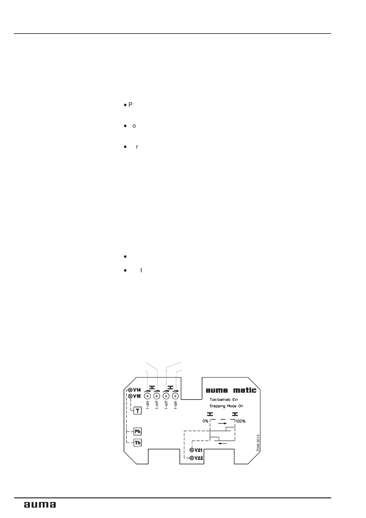
17.1 Function of the diagnosis LEDs (timer)
V14 is illuminated: Phase failure and/or motor protection tripped,
Reset by selector switch to position III at local controls
V15 is illuminated: Torque fault: Torque switch operated in
mid-travel
V21 is illuminated: Stepping mode in direction CLOSE switched on
V22 is illuminated: Stepping mode in direction OPEN switched on
28
Multi-turn actuators SAM Ex 07.1 - SAM Ex 16.1 / SARM Ex 07.1 - SARM Ex 16.1
AUMA MATIC Ex Operation instructions
R11
R10 R12
R13
Figure U: Cover plate timer A1.6



 To Next Page