2. Technical data
2.1 Multi-turn actuators SA(R)M Ex 07.1 -SA(R)M Ex 16.1
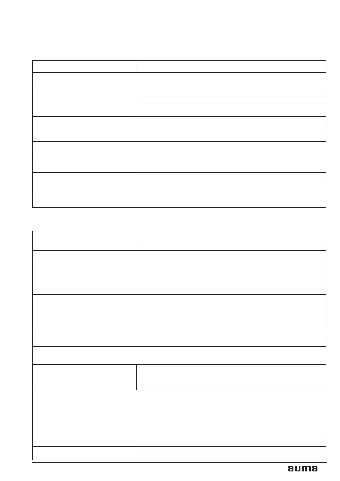
2.2 Controls AUMA MATIC Ex
5
Multi-turn actuators SAM Ex 07.1 - SAM Ex 16.1 / SARM Ex 07.1 - SARM Ex 16.1
Operation instructions AUMA MATIC Ex
Explosion protection:
(according to EN 50 014, 50 018, 50 19)
EEx de IIB T4
Types of duty: SAM Ex:
(acc. to IEC 34-1/ VDE 0530) SARM Ex:
Standard: Short-time duty S2 - 15 min
Standard: Intermittent duty S4 - 25 % ED. Permissible number of starts
refer to Technical data sheet for SAR Ex / name plate
Limit switching: Counter gear mechanism for end positions CLOSED / OPEN
Torque switching: Adjustable torque switching for closing and opening direction
Speeds: Refer to Technical data sheets for SA Ex and SAR Ex
Heater in switch compartment: Approx. 5 W, 24 V, internally supplied
Motor: 3-phase AC motor.
Motor protection: 3 PTC-thermistors and tripping device with reset possibility via selector switch
at local controls
Electrical connection: Terminals
Wiring diagram: Refer to name plate on AUMA MATIC Ex
Ambient temperature:
Standard: −20 °C to +40 °C
Option: −20 °C to +60 °C (special sizing)
Enclosure protection:
(according to 60 529):
Standard: IP 67
Option: IP 68
Explosion protection:
(according to EN 50 014, 50 018, 50 019)
EEx d IIB T4
Types of protection: Motor and switch compartment: EEx d
Terminal compartment: EEx e (optional EEx d)
Corrosion protection: Standard: KN
Option: KS, KX
Integral controls AUMA MATIC Ex, type AM Ex 01.1 and AM Ex 02.1
Explosion protection: See multi-turn actuator
Voltage supply Refer to name plate
Motor controls Reversing contactors Mechanical, electrical, electronically interlocked, max. 690 V AC, max. 7,5 kW
External control voltage Standard: 24V DC, (galvanically isolated from internal voltage supply)
Binary inputs (input signals)
Galvanic isolation
Nominal voltage
Current input
Standard: OPEN-STOP-CLOSE
Option: Switch-over AUTOMATIC-MANUAL
1)
for input signals OPEN-CLOSE
Opto-isolators
24 V DC, from internal power supply (max. 50 mA load) or from external source
10 - 15 mA per input
Analogue inputs (option) See positioner
Relay outputs
–
Collective fault signal:
Phase failure/ motor protection tripped/ torque fault: Torque switch operated
in mid-travel (can be separated, see table 3, page 20)
–
4 signal relays:
End position OPEN / End position CLOSED / selector switch LOCAL /
selector switch REMOTE
Monitor relay (diagnosis LEDs)
–
Phase failure, motor protection tripped
–
Torque fault: Torque switch operated in mid-travel
Analogue output (Option) Position actual value (galvanically isolated) E2 = 0/4 - 20 mA
Positioner (Option)
–
Input range (position nominal value) E1 = 0/4 - 20 mA
Input resistance 250 Ohm
–
Feedback E2 (position actual value): 0/4 - 20 mA
Emergency operation (EMERGENCY)
(option)
Effective in all 3 selector switch positions LOCAL, OFF and REMOTE (see page 21):
–
End position OPEN
–
End position CLOSED
Timer (option) Parameters Running time/ off time independently adjustable (1-30 seconds)
Local controls Standard: Selector switch LOCAL-OFF-REMOTE, reset motor protection,
lockable
Push-buttons OPEN-STOP-CLOSE
Option: Indication lights for end position OPEN, FAULT, end position
CLOSED
Enclosure protection Standard: IP 67
Option: IP 68
Temperature
range
Standard: −20 °C to + 40 °C
Option: −20 °C to + 60 °C (special sizing)
Electrical connection see clause 7, page 10
1) Only in conjunction with the positioner

 Loading...


