Electric Rotary Actuators 2SA7
Technical Data
Y070.304/EN Page 17
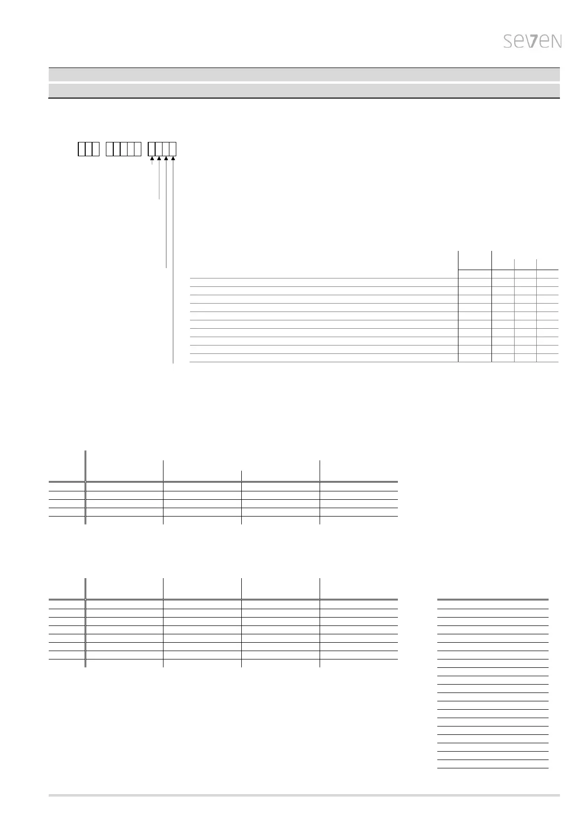
Electrical data – Control and feedback signals
1 2 3 4 5 6 7 - 8 9 10 11 12 13 14 15 16
2SA7
- -
3
ECOTRON: 3 binary inputs 24/48 V DC (OPEN, CLOSE, STOP), 5 binary outputs 24/48 V DC
1 analog output 4 – 20 mA (actual position value), segment display (symbols for parameterization/commissioning)
4
PROFITRON: 5 binary inputs 24/48 V DC (OPEN, CLOSE, STOP, EMERGENCY, Mode), 8 binary outputs 24/48 V DC,
1 analog output 0/4 – 20 mA (actual position value), multicolor graphic display with status indication
A
electronics unit without hardware extension
B
relay board with 5 outputs for ECOTRON, 8 for PROFITRON
C
PROFIBUS DP 1 channel - with V1 and V2 services
D
PROFIBUS DP 2 channel - with V1 and V2 services
E
MODBUS RTU 1 channel
F
MODBUS RTU 2 channel
J
HART (only PROFITRON) ECOTRON PROFITRON
K
HART + relay board (only PROFITRON)
2SA7. 2SA70 2SA73 2SA75
A
standard software-function X X X X
B
positioner X X
C
process controller X
D
travel dependent output speed adjustment X X X
E
positioner + travel dependent output speed adjustment X X
F
external analog output speed setpoint X X X
G
positioner + external analog output speed setpoint X X
H
positioner with split-range functionality X X
J
travel dependent freely adjustable positioning times X X X
K
positioner + travel dependent freely adjustable positioning times X X
L
process controller + travel dependent freely adjustable positioning times X
4
round plug
Note: All set and parameterized values are stored in non-volatile memories (EEPROM)!
Signal assignment for the binary outputs
- for ECOTRON
(also refer to wiring diagrams, signals 1-5):
Signaling set (set 1 to 4 can be adjusted locally in the segment display of the actuator)
Output default setting
optional sets
with option „Y12“
Set 1 Set 2
Set 3
Set 4
1 Travel end OPEN NO End position OPEN NO End position OPEN NO Travel end OPEN NO
2 Travel end CLOSE NO End position CLOSED NO End position CLOSED NO Travel end CLOSE NO
3 Torque CL/OP reached NC Blinker NO Fault NC Ready+Remote NO
4 Ready+Remote NO Ready+Remote NO Local NO Torque OPEN reached NC
5 Warning motor temp. NC Warning motor temp. NC Warning motor temp. NC Torque CLOSE reached NC
NO = active high, NC = active low
- for PROFITRON (also refer to wiring diagrams, signals 1-8):
Optional free assignment of outputs,
NO/NC optional
(can be changed locally)
Output default setting with option „Y12“ with option „Y15“ with option „Y90“
1 End position OPEN NO Intermediate contact OP NO Intermediate contact OP NO Intermediate contact OP NO End position CLOSED
2 End position CLOSED NO Intermediate contact CL NO Intermediate contact CL NO Intermediate contact CL NO End position OPEN
3 Torque OPEN reached NC Ready+Remote NO Torque OPEN reached NO Torque OPEN reached NO Torque CLOSE reached
4 Torque CLOSE reached NC Torque OPEN reached NC Torque CLOSE reached NO Torque CLOSE reached NO Torque OPEN reached
5 Fault NC Torque CLOSE reached NC Ready+Remote NO
Local NC
Torque CL/OP reached
6 Local NO Local NO Local NO
Fault NC
Fault
7 Blinker NO Warning motor temp. NO Blinker NO
Not used
Blinker
8 Warning motor temp. NC Fault external voltage NC Warning motor temp. NO
Not used
Ready
Ready+Remote
NO = active high, NC = active low Local
Intermediate contact CL
Intermediate contact OP
Fault motor temperature
Warning motor temp.
Fault external voltage
Maintenance
Run indication CLOSE
Run indication OPEN
Run indication OPEN/CLOSE
Blinker+ End position CLOSED
Blinker+ End position OPEN
 Loading...