Electric Rotary Actuators 2SA7
Technical Data
Page 8 Y070.304/EN
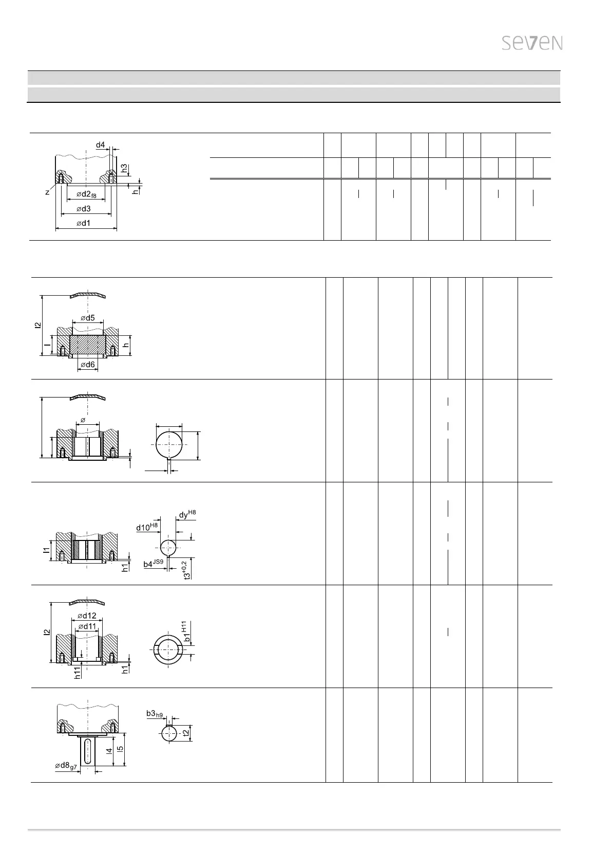
Flange sizes
Rotary actuator
type
2SA7 . 10 11
21
31 32
42
33
43
53 54
64
75 86
Flange size DIN ISO 5210 F07 F10
F10
F12 F14 F16 F25
F30
as per DIN 3210
0
0
1/2 3
4
5
d1 90 125
125
8)
150
8)
175 210 210 300 350
d2 55 70 60 70 60 85 100 130 200 160 230 180
d3 70 102 102 125 140 165 254 298 300
d4 M8 M10 M10 M12 M16 M20 M16 M20
z
4 4 4 4 4 4 8 8
h 3 3 3 3 4 5 5 5
h3 12 17 17 20 25 32 24 30
Output shaft dimensions
Hollow shaft with threaded bush form A as per DIN ISO 5210 and
form A as per DIN 3210
d6
max.
2)
26 32 48 48
52
4)
65 75 77
80
5)
d5 32 34 55 55 55 80 80 80 92
h 38 48 86 86 62 108 77 126 155
l 37 47 85 85 61 108 76 126 155
l2 175 173 267 267 243 347 316 691 782
Thrust max. [kN]
7)
40 60 100 120 120 160 160 350 450
Bore with keyway
d7 28 42 42 50 60 80 100 120
d5
28 34 42 50 55 60 80 80 80
b1 8 12 12 14 18 22 28 32
t1 31.3 45.3 45.3 53.8 64.4 85.4 106.4 127.4
l1 36 45 45 60 65 70 87 139 139
h1 0 0 0 0 0 0 2 2
l2 150 123 210 210 178 280 236 583 583
Bore with keyway
d10 16 20 20 25 30 40 50 60
d
max. 28 30 42 50 45 60 60 80 95
d
max.
50
60
70 100
b4 5 6 6 8 8 12 14 18
t3 18.3 22.8 22.8 28.3 33.3 43.3 53.8 64.4
l1 36.5 45 52 60 65 70 80 139 139
h1 0 0 0 0 0 0 2 2
Hollow shaft with claw coupling
d12
42 42
60
80 100 120
d11
28 28
38 47 64 75
b1
14 14
20 24 30 40
h1
0 0
0 0 2 2
h11
9 9
10 12 11 13
l2
123 210
178 280 236 583 583
Free shaft end with featherkey form D as per DIN 3210
d8
20 20
30 40 50 60
l4
50 50
70 90 110 120
l5
55 55
76 97 117 127
b3
6 6
8 12 14 18
t2
22.5 22.5
33.0 43.0 53.5 64.0
1)
number of tapped holes d4
2)
max. diameter for the spindle
3)
max. diameter for the spindle, if spindle protection tube is necessary; see dimension d6max. (form A)
4)
for version
with spindle protection tube max. 50 mm
5)
max. ø77 for spindle stroke ≥ 541 mm for form A resp. ≥ 348 mm for form B1 (dimensions from connection flange)
6)
with adaptation flange
(height on request)
7)
only applies to ON-OFF duty and inching/positioning duty, for modulating duty on request
8)
175 mm with output shaft form A
form B3 as per DIN ISO 5210 and
form E as per DIN 3210;
form B2/B4 (dy max.)
form C as per DIN 3338 and
form C as per DIN 3210
form B1 as per DIN ISO 5210 and
form B as per DIN 3210
l1
d5
h1
l2
d7
H9
t1
+0,2
b1
JS9