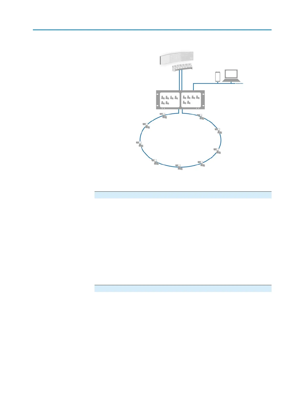
Figure 6: SIMA² system overview (example)
Hardware
Hot standby
System redundancy
Generally, actuators are controlled by SIMA² via a redundant fieldbus connection.
To increase communication availability to the actuators, different redundancy options
are available. A special configuration is the hot standby system redundancy. SIMA
B operates as backup in hot standby operation to SIMA A. In case of SIMA A failure,
SIMA B immediately takes over control of actuators.
Fieldbus interfaces
Into the field: Modbus RTU (single-channel or redundant), Modbus loop redundancy
●
Supporting up to 247 actuators per network. Maximum 4 networks are possible
for each SIMA².
To the host: Modbus RTU and TCP/IP (respectively single-channel or redundant)
●
Operation variants: By means of integrated touchscreen and remote operation
via web browser (computer/laptop/smartphone/tablet)
●
Access to all control and interface components as well as operation elements
from the front panel.
Software
●
Intuitive, graphic user interface.
●
Complete operation of field devices via operation window.
●
Monitoring host signals, control commands, status and warning signals
●
Supports several languages
11
SIMA² Master Station
MODBUS RTU, MODBUS TCP/IP to DCS Identification