10. Technical data
Information
The following tables include standard and optional features. For detailed information
on the customer-specific version, refer to the order-related data sheet.The technical
data sheet can be downloaded from the Internet in both German and English at ht-
tp://www.auma.com (please state the order number).
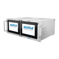
10.1. Technical data SIMA² Master Station
General information
SIMA² Master Station for controlling and supervising AUMA actuators and for easier integration into host systems.
Features and functions
Housing for installation in 19" systems
Dimensions: 4 HE / 84 TE
Integral 7” multi-touchscreen as user interface
Standard:Housing
Housing for installation on control cabinet mounting plate
Dimensions (W x H x D): 483 x 177 x 340 mm
Options:
Desktop housing with front handle and knuckle feet
1-phase AC current: 110 – 240 V AC +/–10 %, 50/60 Hz +/–10 %Standard:Power supply
Mains frequency
DC current: 24 V DC, approx. 1 AOption:
Connection via IEC device plug (type C14) at the housing rearStandard:Type of connection (customer con-
nections)
Lateral arrangement of IEC device plug (type C14)
1)
Option:
Approx. 20 W per SIMA² subsystem
2)
Power consumption
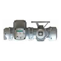
The following AUMA actuators can be connected to SIMA²:
●
Multi-turn actuators (SA .2, SAR .2, SAV .2, SARV .2) or part-turn actuators (SQ .2, SQR .2) in
combination with AC 01.2 or ACV 01.2 actuator controls
●
Multi-turn actuators (SAEx .2, SAREx .2, SAVEx .2, SARVEx .2) or part-turn actuators (SQEx .2,
SQREx .2) in combination with ACExC 01.2 bzw. ACVExC 01.2 actuator controls
●
Multi-turn actuators of the iMatic (DiM(Ex), DiMR(Ex)) type range as well as part-turn actuators of
the DPiM(Ex) type range
●
Multi-turn actuators of type range SEVEN
●
Valve actuators of type ranges SVC and SVM
●
Part-turn actuators of type ranges SGC and SGM
Other field devices with Modbus RTU on request
Supported field devices
Communication to the actuators is established via RS-485 with Modbus RTU
●
Use of twisted, screened RS-485 copper cable in compliance with IEC 61158
●
RS-485 ports accessible from the front side (hidden by hinged fold-out front doors)
Modbus RTU:
●
Fieldbus termination can be activated at the RS-485 communication interfaces
●
Connection of the RS-485 communication cables via spring clamp terminals:
Cross section of spring clamp terminals:
●
-
Single strand: 0.08 – 2.5 mm²
-
Fine stranded: 0.25 – 2.5 mm², with wire end sleeves up to 1.5 mm²
●
Modbus RTU communication parameters:
-
Supported baud rate: 0.3 – 115.2 kbit/s
-
Supported transmission formats: 8 data bits, 1 or 2 stop bits; parity: even, odd or none.
Communication to field devices
Each SIMA² supports up to four different, galvanically and logically separated fieldbus
networks to the actuators with the following characteristics:
●
Einkanalige bzw. redundante Linientopologie (verfügbar mit Modbus RTU)
-
Cable length without repeater max. 1.2 km, with repeater approx. 10 km
-
Number of actuators: without repeater max. 32, with repeater max. 247
●
Redundant loop topology:
-
Automatic and interference-free changing of the communication path in case of
a fault within the RS-485 loop system.
-
Repeater function within the actuator controls, thus, no external repeaters are re-
quired for cable lengths of max. 1.2 km between actuators
3)
-
Cable length: Max. 296 km (without external repeaters)
-
Number of actuators: Max. 247
Options:
33
SIMA² Master Station
MODBUS RTU, MODBUS TCP/IP to DCS Technical data