7.2. Indications on the system components
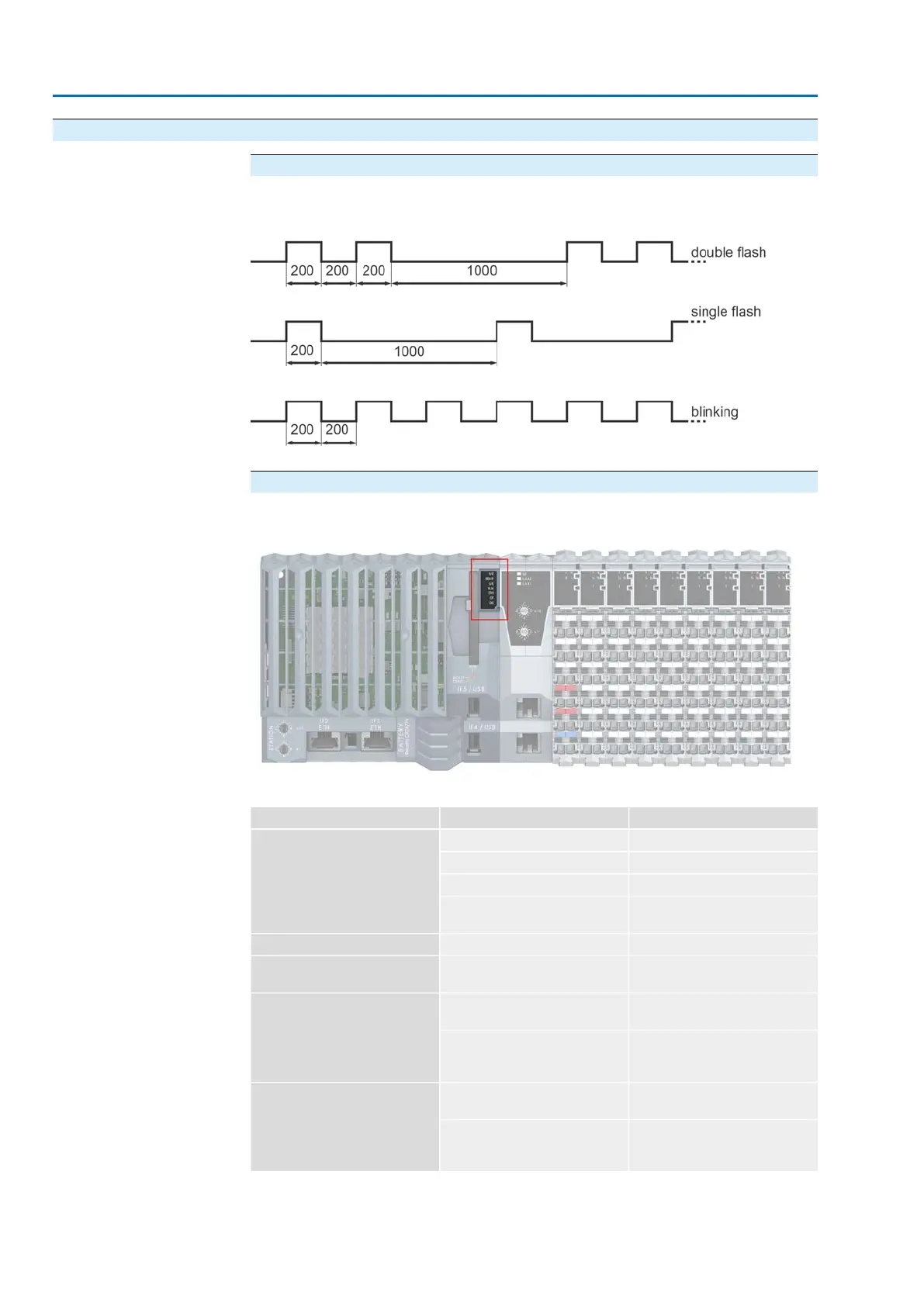
Blinking patterns
Figure 19: Blinking patterns in [ms]
CPU
Figure 20: CPU LEDs
Table 14: Description of CPU LEDs
DescriptionStatusLED
Application is runningIlluminated in greenR/E
Boot mode at system startBlinking in green
Boot mode during firmware updateGreen double flash
Fatal error (AUMA service re-
quired)
Illuminated in red
Boot modeIlluminated in yellowRDY/F
Interface is operated as Ethernet
interface
Illuminated in greenS/E
Connection from IF3 to remote
station was established
Illuminated in greenPLK
Connection from IF3 to remote
station was established and Ether-
net activity present
Blinking in green
Connection from IF2 to remote
station was established
Illuminated in greenETH
Connection from IF2 to remote
station was established and Ether-
net activity present
Blinking in green
22
SIMA² Master Station
Indications MODBUS RTU, MODBUS TCP/IP to DCS