7. Indications
7.1. Indications on the housing
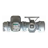
SIMA² housing is equipped with a Power LED and an Info LED for each SIMA²
subsystem to visually signal different states. These LEDs are located respectively
in the right and left lower edge of the SIMA² face plate.
Figure 18: SIMA² LEDs of face plate
[1] Power LED
[2] Info LED
If two SIMA² subsystems are located in one housing, the LEDs on the left side of the
housing are active for the subsystem installed at the left. The LEDs on the right side
of the housing are active for the subsystem installed at the right. This is the case of
the hot standby system redundancy for example.When dealing with a single Master
Station and thus only one SIMA² subsystem is installed within one housing, the LEDS
on the left housing side apply for the screen located on the right..
The following LEDs may either be illuminated permanently or flash at a rate of either
200 ms or 500 ms (slow).The following table explains the states signalled by the
LEDs.
Table 13: Description of the LEDs on the face plate.
DescriptionInfo LEDPower LED
Power supply is available and all actuators can be addressed.Illuminated in
green
Illuminated in
green
Power supply is available and SIMA² is in operation mode.
Slowly blinking
in green
Illuminated in
green
SIMA² is booting and in initialisation phase.Blinking altern-
atively in
green and red
Illuminated in
green
Live list fault, at least one actuator cannot be addressed.Illuminated in
red
Illuminated in
green
●
CPU is without power supply
●
CPU is defective
●
Software does not boot
●
Snapshot transfer executed via USB
●
Loop interrupted (for loop redundancy only)
Blinking in redBlinking in
green
21
SIMA² Master Station
MODBUS RTU, MODBUS TCP/IP to DCS Indications