4. Assembly
4.1. Notes for installation
SIMA² is available in the following variants: Standard housing for 19” rack mounting,
as bench device, for wall mounting or top-hat rail mounting (on request).
When used as bench device, the standard housing can be equipped with stands
elevating the SIMA² housing.
Information
When installing or setting up, the following must be heeded:
●
Housing, components and mains connector require sufficient space.
●
Housing and components require sufficient ventilation.
●
Doors of standard housing require space for swinging open.
●
Optional handles increase space requirements at the front.
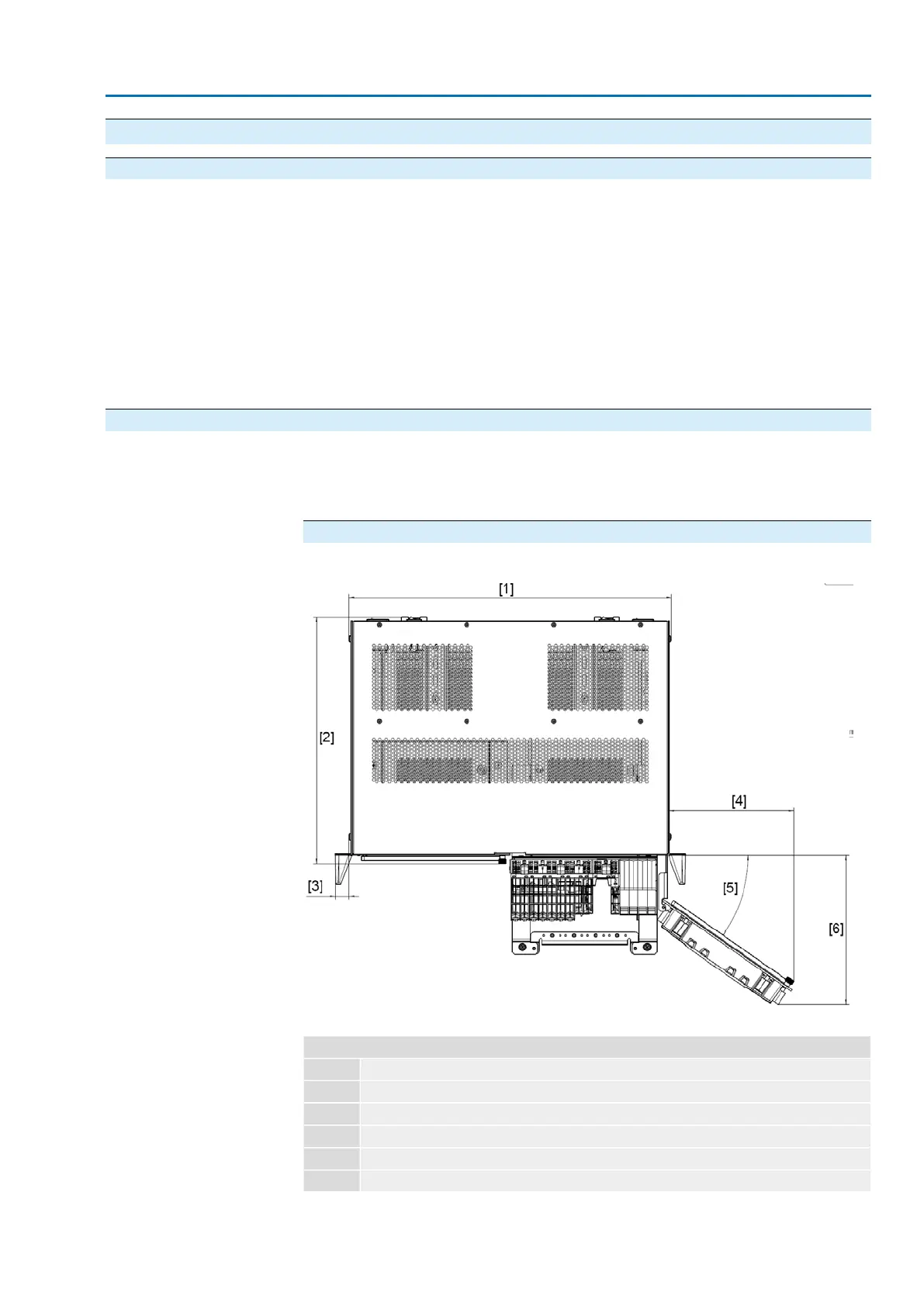
4.2. Dimensions
The following drawings indicate the dimensions of the various SIMA² variants.
Information
The illustrations show an example of SIMA² in version “hot standby system redund-
ancy in one joint housing”.
Standard housing
Figure 7: SIMA² standard housing, top view with open doors
Table 3:
Legend
444.8 mm[1]
340 mm[2]
19.1 mm[3]
172 mm[4]
35°[5]
205 mm[6]
13
SIMA² Master Station
MODBUS RTU, MODBUS TCP/IP to DCS Assembly