Technical data
Table 10: RWG 4020
2-wire system3-wire or 4-wire systemData
4 – 20 mA0 – 20 mA, 4 – 20 mAOutput current I
a
14 V DC + (I x R
B
), max. 30 V24 V DC (18 – 32 V)Power supply U
V
1)
20 mA24 mA at 20 mA output currentMax. current consumption
(U
V
– 14 V)/20 mA
600 ˖
Max. load R
B
0.1 %/V0.1 %/VImpact of power supply
0.1 %/100 ˖0.1 %/(0 – 600 ˖)
Load influence
< 0.3 ‰/KTemperature impact
–60 °C to +80 °CAmbient temperature
2)
5 k˖
Transmitter potentiometer
Power supply possible via: AC, AM controls or external power supply1)
Depending on temperature range of the actuator: Refer to name plate2)
Setting elements
The RWG is housed in the actuator switch compartment.The switch compartment
must be opened to perform any settings. Refer to <Switch compartment: open>.
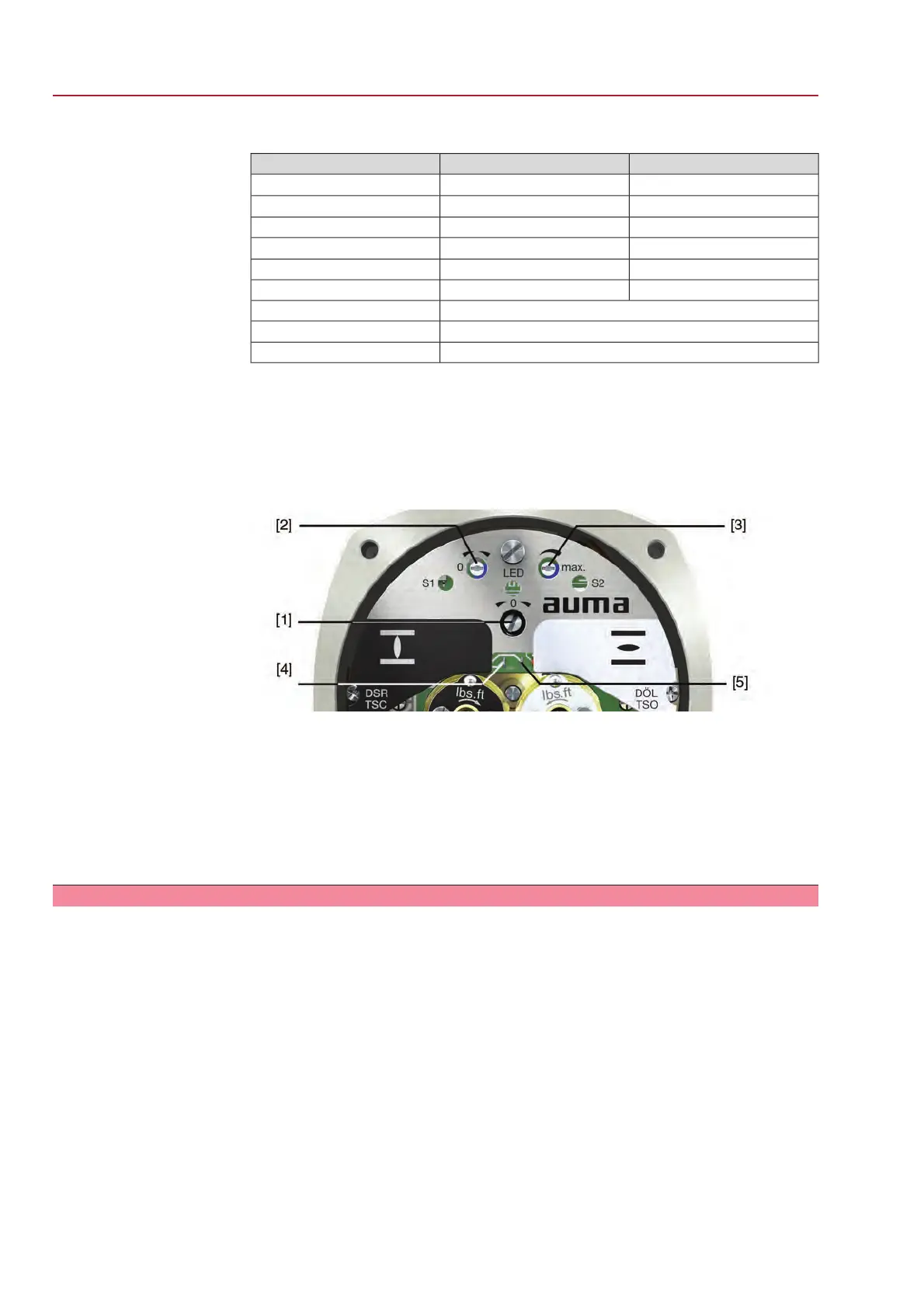
Setting is made via three potentiometers [1], [2] and [3].
Figure 29: View on control unit when switch compartment is open
[1] Potentiometer (travel sensor)
[2] Potentiometer min. (0/4 mA)
[3] Potentiometer max. (20 mA)
[4] Measuring point (+) 0/4 – 20 mA
[5] Measuring point (–) 0/4 – 20 mA
The output current (measuring range 0 – 20 mA) can be checked at measuring points
[4] and [5].
9.10.1. Measuring range: set
For measuring range setting, voltage must be applied at the position transmitter.
1. Move valve to end position CLOSED.
2. Connect ammeter for 0 – 20 mA to measuring points [4 and 5].
3. Turn potentiometer [1] clockwise to the stop.
4. Turn potentiometer [1] slightly in opposite direction.
5. Turn potentiometer [2] clockwise until output current starts to increase.
6. Turn potentiometer [2] in opposite direction until the following value is reached:
- for 0 – 20 mA approx. 0.1 mA
- for 4 – 20 mA approx. 4.1 mA
➥
This ensures that the signal remains above the dead and live zero point.
7. Move valve to end position OPEN.
8. Set potentiometer [3] to end value 20 mA.
40
SQ 05.2 – SQ 14.2/SQR 05.2 – SQR 14.2
Commissioning (basic settings) AM 01.1


 To Next Page