Information If the controls are equipped with a positioner, switches 1 and 2 (operation commands
from remote) must be in position OFF (push-to-run operation).
10.4. Running indication (blinker transmitter): activate/deactivate
— (Option) —
If the actuator is equipped with a blinker transmitter (wiring diagram designation:
S5), indication lights (OPEN/CLOSE) on the local controls can be used as running
indication. If the running indication is active, the respective indication light blinks
during actuator operation.
The running indication is activated/deactivated via a DIP switch on the logic board.
→
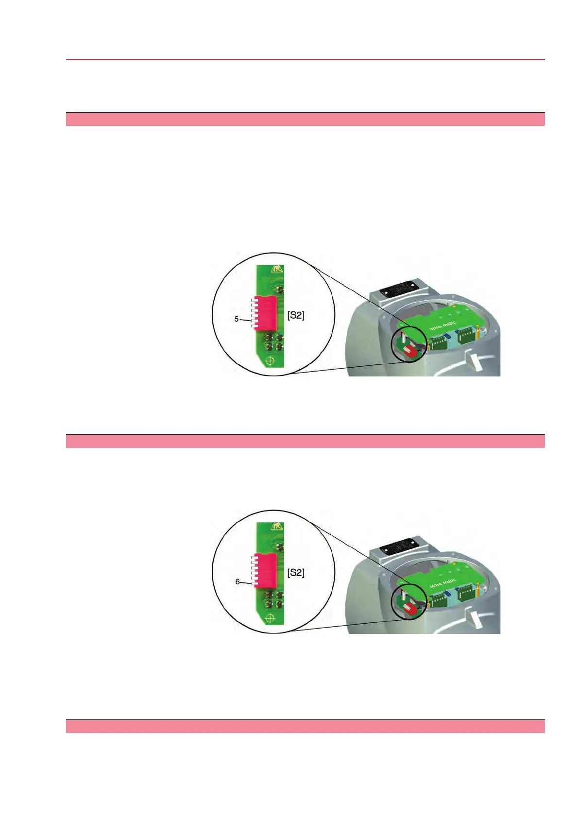
Set running indication (blinker) via DIP switch [S2].
Figure 32: DIP switch on logic board
[S2] 6-way DIP, switch 5
➥
Switch 5 in lower position (position ON): Running indication is deactivated.
➥
Switch 5 in upper position (position OFF): Running indication is activated.
10.5. Torque fault in collective fault signal: activate/deactivate
The torque fault signal is activated/deactivated via a DIP switch on the logic board.
→
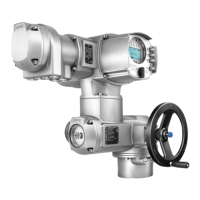
Activate/deactivate signal via DIP switch [S2].
Figure 33: DIP switch on logic board
[S2] 6-way DIP, switch 6
➥
Switch 6 in lower position (position ON):The signal "Torque fault in collective
fault signal" is activated.
➥
Switch 6 in upper position (position OFF):The signal "Torque fault in collective
fault signal" is deactivated.
10.6. Positioner
— (Option) —
45
SQ 05.2 – SQ 14.2/SQR 05.2 – SQR 14.2
AM 01.1 Commissioning – controls settings


 To Next Page