1.2 Conductor terminals of AURATON 2020
The conductor terminals may be accessed after
removing the cover of the front controller panel,
batteries, and 2 screws fixing the protection plate.
There are three terminals, marked by COM, NO,
and NC. This is a typical unipole two-state relay.
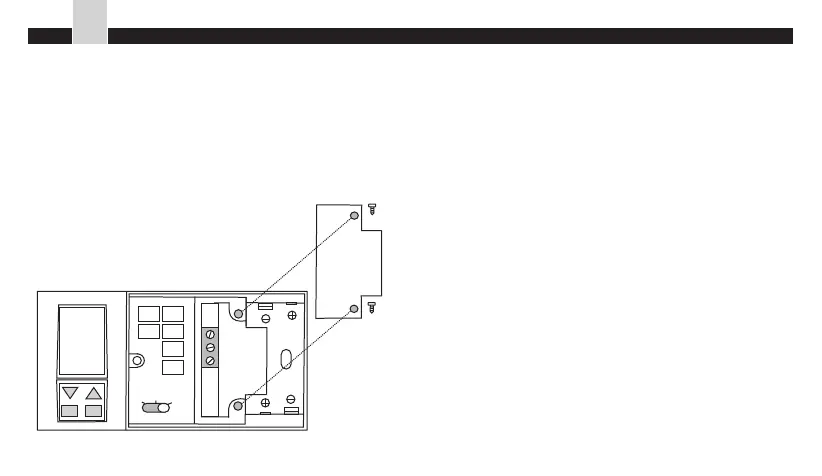
1.3 Assembly of the AURATON 2020 controller
The controller is assembled with the help of a
pattern. Bore two holes of the diameter of 6mm in
the wall. Drive the bolts and tighten the controller
with screws, the left-hand screw longer than the
right-hand one.
Note: In case of installation of a controller
provided with a floor sensor pay attention to
Figure inserted in Section 18.3, page 24.
Note: In case of a wooden wall the pins should not
be used. Drill the holes of 2.7mm instead of 6mm
diameter and fasten the screws directly to the
wood.
PROG
DAY
RETURN
HOUR
MIN
FILTER
OFF
HEAT
5°C
AUTO
MAN
NC
COM
NO
33
EN
AURATON 2020 - Installation